Installation, cont’d, Tp cable termination, Remote connection – Extron Electronics SW MTP T Series User Guide User Manual
Page 12: Caution
SW MTP T Series Switchers • Installation
SW MTP T Series Switchers • Installation
Installation, cont’d
2-10
6
Audio output connector
— Insert a 3.5 mm, 5-pole, one-piece
captive screw audio connector into this connector for stereo
audio output. Wire the connector as shown in figure 2-9.
CAUTION
Connect the sleeve to ground (Gnd). Connecting
the sleeve to a negative (-) terminal will damage the
audio output circuits.
Unbalanced Output
Tip
See caution
Sleeve
Tip
See caution
Balanced Output
Tip
Ring
Sleeve (s)
Tip
Ring
Figure 2-9 — Captive screw audio connector wiring
Remote connection
7
Remote RS-232/contact closure connector
— Connect a
computer or control system to this 9-pin D connector to
allow remote control using the Simple Instruction Set™
(SIS™) or the Extron graphical control program for
Windows (see figure 2-10). See chapter 4, Remote Control,
for details.
You can also connect a KP 6 remote control keypad
(part #60-111-20) or an IR 102 Kit infrared remote control
(part #70-224-01) system to this connector.
REMOTE
PIN
RS-232
Contact
Closure
Function
1
—
In #1
Input #1
Input #2
Input #3
Input #4
Input #5
Input #6
2
TX
—
Transmit data
3
RX
—
Receive data
4
—
In #2
5
Gnd
Gnd
Ground
6
—
In #3
7
—
In #4
8
—
In #5
9
—
In #6
Figure 2-10 — Remote connector pinout
The switcher can only be controlled by an RS-232 device
OR
a contact closure device, not both.
The cable used to connect the Remote port to a computer,
control, contact closure device, or IR control kit may
need to be modified by removing pins or cutting wires.
If unneeded pins are connected, the switcher may hang
up. See chapter 4, Remote Control, for additional
information.
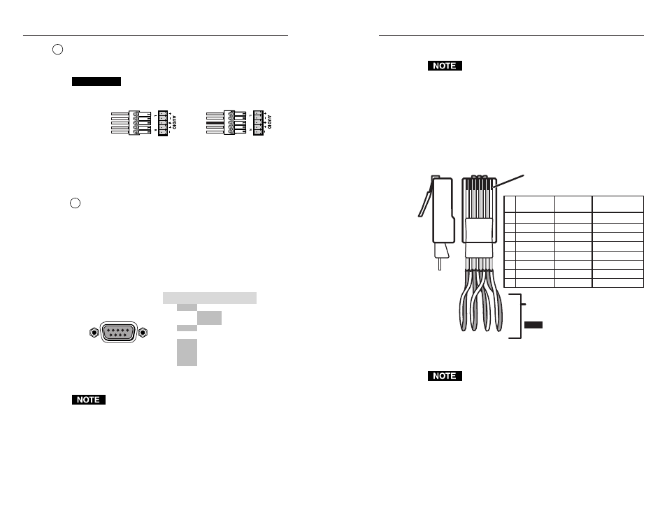
TP Cable Termination
RJ-45 termination must comply with the
TIA/EIA T 568A or TIA/EIA T 568B wiring standards
for all connections. If you are using Enhanced Skew-
Free A/V UTP cable, then you should use the
TIA/EIA T 568A standard only.
Figure 2-11 details the recommended termination of TP cables
with RJ-45 connectors in accordance with the TIA/EIA T 568A
or TIA/EIA T 568B wiring standards. You can use either
standard with CAT 5 cable, but ensure that you use the same
standard on both ends of the cable.
5
Pin
1
Red+/V. sync+
2
Red–/V. sync–
3
Mono audio+
Green–
6
Mono audio–
7
Blue+/H. sync+
8
Blue–/H. sync–
4
Wire color
White-green
NOTE
If you are using Enhanced Skew-Free™
A/V cable, use the TIA/EIA T 568A
standard only.
Green
White-orange
White-blue
Orange
White-brown
Brown
Wire color
568 A
568 B
Signal
White-orange
Orange
White-green
White-blue
Green
White-brown
Brown
Clip Down
Side
1
1&2
3&6 4&5
7&8
2 3 4 5 6 7 8
1
Pins
2 3 4 5 6 7 8
RJ-45
connector
Twisted
Pairs
Green+
Blue
Blue
Figure 2-11 — TP cable termination
Enhanced Skew-free A/V cable is not recommended for
Ethernet/LAN applications.
This cable is specially designed for compatibility with
Extron’s Twisted Pair products, wired using the
TIA/EIA 568 A standard.
The green, brown, and blue pairs of this cable have
virtually identical lengths and should be used to
transmit the RGB signals.
The orange pair of this cable has a different length and
should not
be used to transmit the RGB signals.
2-11