Controls and indicator, Operation, Specifications – Extron Electronics SEQ 100 15HD User Guide User Manual
Page 12: Versatools, Seq 00 skew equalizer, cont’d
VersaTools
®
SEQ 100 Skew Equalizer
VersaTools
®
SEQ 00 Skew Equalizer, cont’d
VersaTools
®
SEQ 100 Skew Equalizer
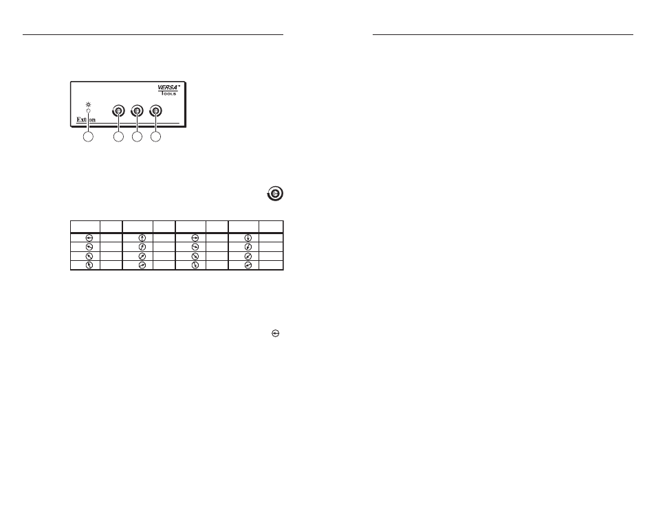
Controls and Indicator
a
Power LED —
This front panel LED (figure 14) lights to indicate
that the SEQ 100 Skew Equalizer is receiving power.
GREEN
RED
BLUE
SEQ 100 15HD
1
2
2
2
Figure 14 — SEQ 100 Skew Equalizer front panel
b
Red, Green, and Blue skew adjustment rotary switches —
These 16-position rotary switches delay the associated
red, green, or blue video signals by approximately 3
nanoseconds per position, up to 39 nanoseconds.
See the table below:
Position Delay Position Delay Position Delay Position Delay
1
2
3
0 ns
3 ns
6 ns
9 ns
5
6
7
10 ns
13 ns
16 ns
19 ns
9
10
11
20 ns
23 ns
26 ns
29 ns
13
14
15
0
4
8
12
30 ns
33 ns
36 ns
39 ns
Operation
When the video source, transmitter, SEQ 100, receiver, and
display are powered up, the system is fully operational. Adjust
the equalization as follows:
1.
Rotate all three skew adjust rotary switches to the zero ( )
position.
2
.
Use UTP cable test equipment or examine the displayed
video image with a critical eye to determine which video
signal, red, green, or blue, is most shifted to the left.
N
A crosshatch test pattern is ideal for determining pair
skew.
3
.
Adjust the left-shifted video signal’s rotary switch
clockwise one step at a time while monitoring the display.
Step the switch until the video signal is properly converged.
N
The SEQ 100 cannot shift the rightmost video image to
the left.
4
.
If either of the other video signals is misconverged, repeat
steps 2 and 3.
Specifications
Video
Gain ................................................ Unity
Video input
Number/signal type ..................... 1 RGBHV, RGBS, RGsB, component video
Connectors .................................... 1 female 15-pin HD
Nominal level ................................ 1 Vp-p for Y of component video
0.7 Vp-p for RGB and for R-Y and B-Y of
component video
Minimum/maximum levels ........ Analog: 0.3 V to 1.45 Vp-p with no offset
at unity gain
Impedance ..................................... 75 ohms
Horizontal frequency .................... 15 kHz to 130 kHz
Vertical frequency .......................... 30 Hz to 150 Hz
Video output
Number/signal type ..................... 1 RGBHV, RGBS, RGsB, component video
Connectors .................................... 1 female 15-pin HD
Nominal level ................................ 1 Vp-p for Y of component video
0.7 Vp-p for RGB and for R-Y and B-Y of
component video
Minimum/maximum levels ........ 0.3 V to 1.45 Vp-p (follows input)
Impedance ..................................... 75 ohms
Sync (pass-through)
Input type ...................................... RGBHV, RGBS, RGsB
Output type .................................... RGBHV, RGBS, RGsB (follows input)
Input/output level ....................... TTL: 5.0 Vp-p, unterminated
Input impedance .......................... 75 ohms
Output impedance ....................... 75 ohms
Max input voltage ........................ 5.0 V p-p
Polarity............................................ Positive or negative (follows input)