Cabling and setup, If an external supply powers the transmitter – Extron Electronics USB Extenders User Guide User Manual
Page 16
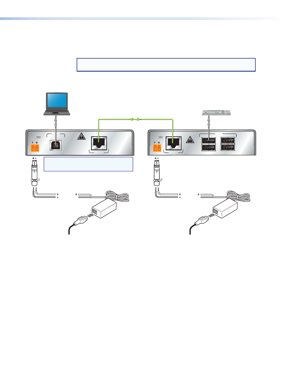
Cabling and Setup
To ensure proper operation, the transmitter, receiver, USB host, and USB peripherals must
be connected properly and in the sequence described below. Connections are the same
regardless of which models (Extender, Extender AAP or Decora) are installed.
NOTE: If the USB host is capable of powering the transmitter (0.4 A maximum), the
external supply for the transmitter is not required.
Power down the USB host PC or laptop connected to the transmitter and all peripherals and
devices connected to the receiver.
USB
USB
HUB
1
2
3
4
POWER
12V
1.0A MAX.
LINK
DO NOT
CONNECT
TO LAN
HOST
POWER
12V
0.4A MAX.
DO NOT
CONNECT
TO LAN
LINK
Ground
+12 VDC
External Power
Supply (optional)
(12 VDC, 1 A )
External Power
Supply (required):
Rack Mount: 12 VDC, 1 A
AAP: 12 VDC, 2 A
Decora: 12 VDC, 1 A
Ground
+12 VDC
Laptop
(USB Host)
Keyboard
(USB Peripheral)
Four USB 2.0 compatible female Type A
connectors provide +5 VDC at up to
500 mA to connected USB peripherals.
NOTE: If the USB host is capable of supplying power,
the transmitter supply is not required.
The receiver must have a power supply connected.
Transmitter
Receiver
UTP or STP CAT5 or better cable.
Terminate both ends identically, in accordance with
either the TIA/EIA T 568A or the TIA/EIA T 568B
wiring standard.
Figure 7.
USB Extender Connection Guide with Two External Supplies
If an external supply powers the transmitter:
1.
Connect twisted pair cable between the transmitter and receiver link connectors.
2.
Connect one included power supply to the USB Extender receiver and one to the
transmitter, then apply power to both. The Power LEDs on both light.
Additionally, with both units powered, the Link LEDs light to indicate connectivity on the
twisted pair link.
3.
Connect a Type A-B USB cable (Type A male to mini Type B male for AAP and Decora Tx)
from the USB host to the USB Extender transmitter.
4.
Apply power to the USB host. After the host has booted, the transmitter Host LED lights to
indicate communication between the host and transmitter. Shortly after, the Host LED on
the receiver lights, then blinks to indicate the host is communicating with the hub controller
(USB Extender receiver).
5.
Connect USB peripherals (keyboard, mouse, scanner, printer, or other USB devices) to the
receiver. As each peripheral is recognized by the host, the respective USB hub port LED
on the receiver front panel lights.
USB Extenders • Installation and Operation
10