Rear panel connections and features, Locations and functions, Locations and functions -3 – Extron Electronics IPL 250 Setup Guide User Manual
Page 13
2-3
Refer also to the IPL 250 Reference Manual at www.extron.com.
IPL 250 • Setup
Rear Panel Connections and Features
Locations and functions
INPUT
LAN
POWER
12V
500mA
MAX
1 2 3 4
COM 3
IR
3
S G S G
TX RX
4
RELAY
3
4
COM1
TX RX
RTS CTS
COM 2
IR
1
S G S G
TX RX
2
RELAY
1
2
MAC: 00-05-A6-XX-XX-XX
S/N:
1
2
7
3
8
4
5
6
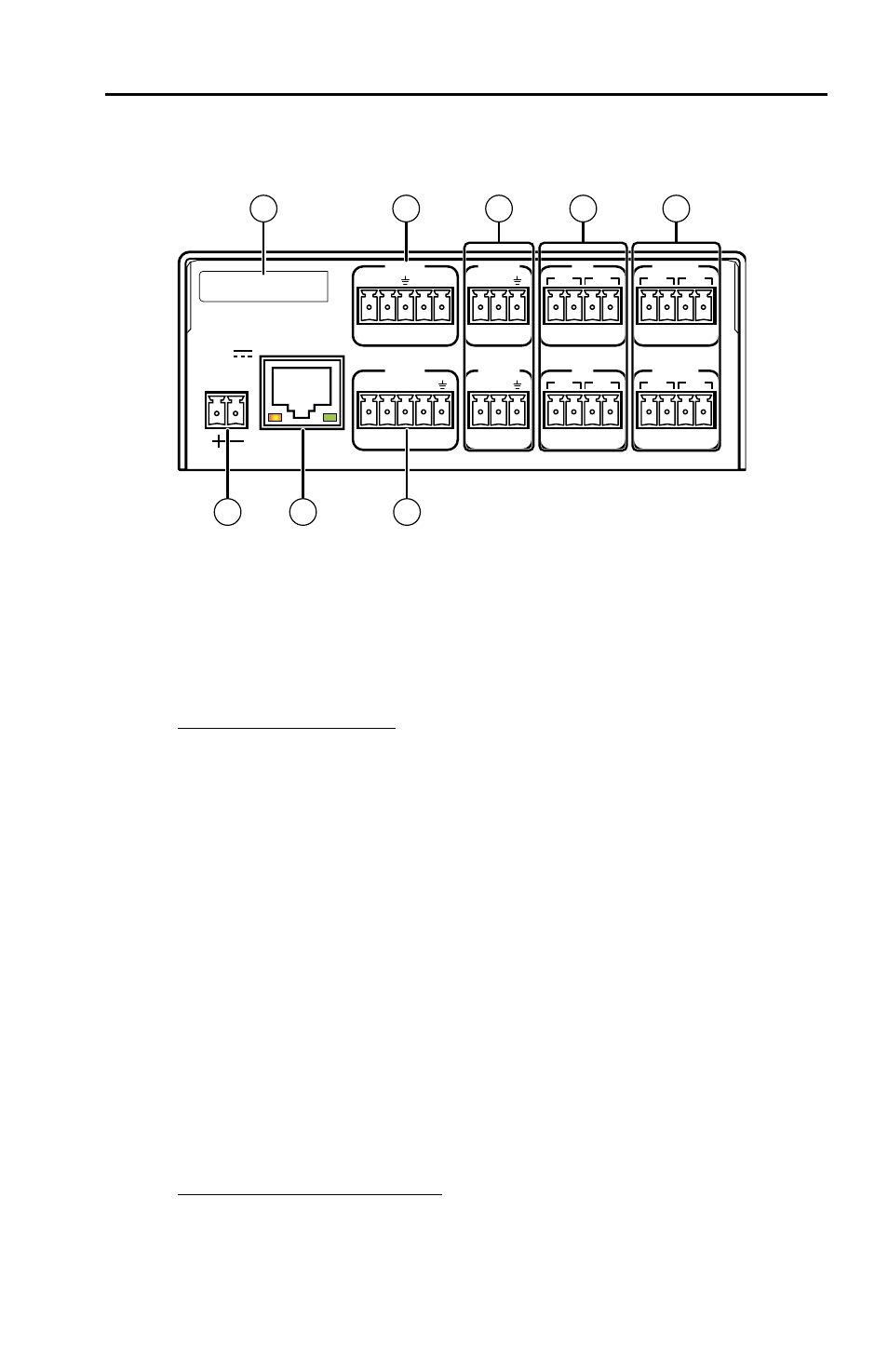
a
Power — Connect the DC power
supply here after making all other
connections.
b
Ethernet (LAN) port — Connect
the unit to an Ethernet network.
LAN port default protocol:
• IPL’s IP address: 192.168.254.254
• Gateway’s IP address: 0.0.0.0
• Subnet mask: 255.255.0.0
• DHCP:
off
• Link speed and duplex level:
autodetected
c
COM 1 serial port — Cable a device
(such as a display) here to control
it using RS-232 communication.
Downloaded control commands
(from device drivers) can be sent
from this port.
d
COM 2 and COM 3 serial ports —
Connect additional devices to these
ports to control them via RS-232.
Protocol can be changed via
software or SIS command; speed can
be set from
300 to 115200 baud
.
COM port (1-3) default protocol:
• 9600 baud
• 1 stop bit
• no parity
• no flow control
N
The 5-pole COM 1 port
supports both hardware
and software flow control.
The 3-pole COM 2 and
COM 3 ports support
software flow control.
e
IR ports (IR) — Connect IR Emitters
or another device's wired IR control
port here to send IR signals (with
or without carrier frequencies) to
display or source devices.
f
Relay ports (Relay 1, 2, 3, 4) —
Connect equipment here that can
be controlled via momentary or
latching contact. A total of 24 V
at 1 A must not be exceeded for
each port. Each relay has two sets
of contacts: by default, one pair
is closed, the other is open. Both
contacts can be used at the same time;
a total of eight sets of contacts can be
used simultaneously. Use software
to change the timeout period.
g
Contact input (Input) ports —
Connect an optional contact closure
device here. Pins 1-4 select inputs
1-4 on a connected switcher or
projector; pin 5 is a ground pin.
h
MAC address — This is the unique
hardware ID number.
See pages 2-4 and 2-5 for wiring diagrams.