Lan/poe (ip) connectors and leds, Mac address, Lan (ethernet) – Extron Electronics IPL Pro Series User Guide PRELIMINARY User Manual
Page 20: Connectors and, Preliminary, Figure 9. lan connector and leds
IPL Pro Series • Hardware Features and Installation
14
C
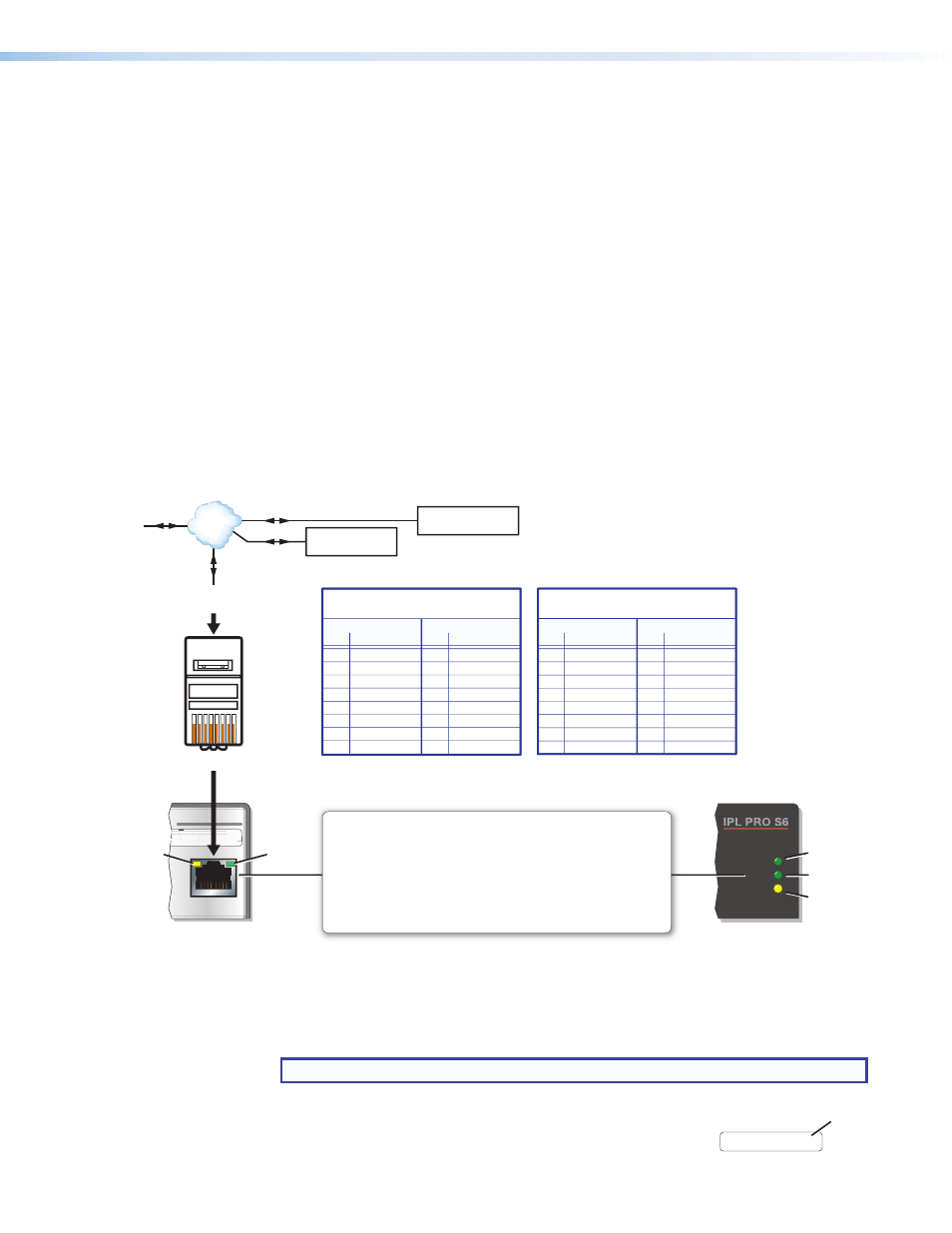
LAN/PoE (IP) connectors and LEDs — To connect the IPL to an Ethernet network
(so you can configure and control the IPL and the devices connected to it), plug a cable
into the LAN RJ-45 socket and connect the other end of the cable to a network switch,
hub, router, or PC connected to a LAN or the Internet.
The IPL Pro Series control processors accept power over Ethernet (PoE) through the
LAN port. Both an external power supply and PoE can be connected to the control
processor simultaneously. The IPL uses PoE when it is available but can switch
seamlessly to the external power supply if the PoE connection is dropped.
Cabling:
•
For 10Base-T (10 Mbps) networks, use a CAT 3 or better cable.
•
For 100Base-T (max. 155 Mbps) or 1000Base-T networks, use a CAT 5 cable.
You must configure this port before using it. Configure the settings via Global
Configurator. See
Software-based Configuration and Control
of this guide for basic information on configuration.
Activity LED (connector and front panel) — This yellow LED blinks to indicate network
activity.
Link LED (connector and front panel) — This green LED lights to indicate a good
network connection.
1000 LED (front panel) — This green LED lights when the unit is connected to a gigabit
network connection.
1000
LINK
ACT
LAN / PoE
I
IPL
PR
PR
O
S
6
5-
5
-A6-
XX-XX-X
X
##
#
##
E###
###
5
5
-
A
6
-
X
X
-
-
X
X
X
-
X
X
A
Rear Panel
Front Panel
RJ-45
Connector
Insert Twisted
Pair Wires
Pins:
1
2
3
4
5
6
7
8
1000 Mbps
Connection
Network is
active.
Data is being
sent/received.
Link
LED
Activity
LED
LAN/PoE (Ethernet)
Default protocol:
• IPL IP address: 192.168.254.
250
• Gateway IP address: 0.0.0.0
• Subnet mask: 255.255.255.0
• DNS address: 127.0.0.1
• DHCP: off
• Link speed and duplex level:
autodetected
• Data rates: 10/100/1000Base-T
Power over Ethernet (PoE):
If PoE is available, the IPL uses PoE.
If PoE is dropped (disconnects), the
IPL switches seamlessly to the
external 12 VDC power supply, if it
is installed.
Default login credentials:
• Username:
admin
• Password:
extron
Ethernet
PC
Touchlink Pro
Touchpanel
Extron Devices
(Switchers, Scalers)
TCP/IP
Network
Straight-through Cable
(for connection to a switch, hub, or router)
End 1
End 2
Pin
Wire Color
Pin Wire Color
1
white-orange
1
white-orange
2
orange
2
orange
3
white-green
3
white-green
4
blue
4
blue
5
white-blue
5
white-blue
6 green 6 green
7
white-brown
7
white-brown
8 brown 8 brown
Crossover Cable
(for direct connection to a PC)
End 1 End 2
Pin
Wire Color
Pin Wire Color
1 white-orange
1
white-green
2
orange
2
green
3 white-green
3
white-orange
4
blue
4
blue
5 white-blue
5
white-blue
6 green
6
orange
7 white-brown
7
white-brown
8 brown 8 brown
T568B
T568A
T568B
TIA/EIA-T568B
The following addresses apply
to control processors.
For single NIC models...
192.168.254.250 = primary/
public NIC
For dual NIC models:
192.168.254.250 = primary/
public NIC
192.168.253.250 = secondary/
private NIC
Per John Spencer, 01/08/14,
“the primary NIC on both
the host AV product and the
integrated control module
must reside on the same
subnet. The primary NIC on
both the host AV product
and the integrated control
module must have unique
IP addresses. For individual
products with multiple NICs,
each NIC should reside on a
different subnet.”
TouchLink Touchpanels will
have the following default IP
address: 192.168.254.251
Keep the “IPL LAN port
defaults” text set to “no
color” (to use as an invisible
text/hyperlink marker).
Figure 9.
LAN Connector and LEDs
•
Use a straight-through cable for connection to a switch, hub, or router.
•
Use a crossover cable for connection directly to a PC. Wire the connector as
shown in the tables above.
NOTE: DHCP is off by default.
D
MAC address — This is the unique user hardware ID number
(MAC address) of the unit (for example, 00-05-A6-05-1C-A0).
You may need this address during configuration.
MAC: 00-05-A6-XX-XX-XX
S/N: ####### E######
MAC
Address
PRELIMINARY