Bidirectional control and communication, Connections and features, Pole com rs-232/rs-422 – Extron Electronics IPL Pro Series User Guide PRELIMINARY User Manual
Page 19: Preliminary, 8 (default) or 7 data bits, 1 (default) or 2 stop bits, Figure 8. wiring com ports for serial control
IPL Pro Series • Hardware Features and Installation
13
Bidirectional Control and Communication Connections and Features
B
5-pole COM ports, RS-232/RS-422*/RS-485* —
Use COM ports for serial control of a display or other device and to receive status
messages from the connected devices. These ports can send
commands from a driver file. RS-232 is the
default mode of operation.
IPL Pro Series serial protocol:
•
300 to 115200 baud (9600 baud = default)
•
8 (default) or 7 data bits
•
1 (default) or 2 stop bits
•
No parity (default), even, odd, mark, or space
parity
•
Flow control support (default = none):
hardware and software (XON, XOFF)
*Supported serial formats vary depending on
the model and the COM port, as shown at
right.
Use the following diagram as a wiring guide to
cable the IPL to other devices.
G
Tx Rx
RTSCTS
COM 1
G
Tx Rx
RTSCTS
COM 4
COM
3
1
2
6
4
5
RTS
CTS
Tx
Rx
COM
RTS
CTS
Tx
Rx
NOTE: If you use cable that has a drain wire, tie the drain wire to ground at both ends.
Strip wires
3/16" (5 mm)
max.
Transmit (Tx)
Receive (Rx)
Projector, Panel
Display, PC, or
Other RS-232,
RS-422, or
RS-485 Device
Request to send
Clear to send
Transmit
Rx Receive
Tx
CTS
RTS
G Ground
T
T
Tx
T
R
Front Panels
Select protocol via software.
COM port default protocol:
• 9600 baud
• 8 data bits • 1 stop bit
• no parity
• no flow control
NOTE: The 5-pole COM ports support both
hardware and software flow control.
Heat Shrink
Heat Shrink
Over Shield Wires
To 5-pole
COM port
RTS = Request to Send
CTS = Clear to Send
Tx = Transmitting Data
Rx = Receiving Data
Serial (COM) Ports
Rear Panels
5-pole COM
(RS-232, RS-422*, RS-485*)
*See the Serial Options
table for which port
supports which standards.
RS-232
Tx
Rx
Ground
RTS
CTS
RS-422*
Tx-
Rx-
Ground
Tx+
Rx+
RS-485*
Ground
5-pole COM Pin Configurations
Data-
(pins 1 & 2
tied together)
Data+
(pins 4 & 5
tied together)
Pin
1 (Tx)
2 (Rx)
3 (G)
4 (RTS)
5 (CTS)
*See the Serial Options table of supported
formats for each port.
Figure 8.
Wiring COM ports for Serial Control
For bidirectional serial communication, the transmit, ground, and receive pins must be wired
at both the IPL Pro Series and the other device. Each projector or other device may require
different wiring. For details, see the manual for that equipment or read the Extron device
driver communication sheet, which is included with the drivers.
NOTE:
Maximum distances between the IPL and the device being controlled may vary up
to 200 feet (61 m). Factors such as cable gauge, baud rates, environment, and output
levels (from the IPL and the device being controlled) all affect transmission distance.
Distances of about 50 feet (15 m) are typically not a problem. In some cases the IPL may
be capable of transmitting and controlling a given device via RS-232 up to 250 feet (76 m)
away, but the RS-232 response levels of that device may be too low for the IPL to detect.
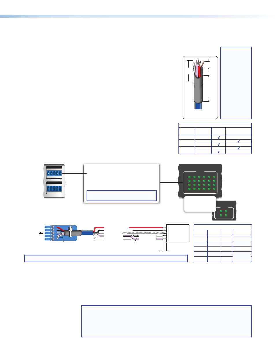
3/16"
(5 mm)
Max.
7/8
"
(22 mm)
Heat
Shrink
on Outer
Jacket to
Inner
Conductor
Transition
Extron
Comm-Link Cable
TIP:
Comm-Link (CTL
and CTLP) cable,
shown at left, is
recommended
for these
connections. For
best results and
to avoid short
circuits, use
shielded wires
or wires insulat-
ed using heat
shrink (instead
of bare wires) for
the common/
drain wires.
RS-232
Only
RS-232, RS-422,
or RS-485
Serial Options
Model
COM Port
1
IPL Pro S1
1
2, 3
IPL Pro S3
1
2, 3, 4, 5, 6
IPL Pro S6
PRELIMINARY