Extron Electronics Extender Plus Series User Guide User Manual
Page 12
Extender Plus Series • Installation and Operation
6
a
EDID Rotary Switch — Position 0 of this 16-position rotary switch is used to record an
EDID from a display. See “
” on page 8.
Positions 1 through F select pre-programmed EDID resolutions. See “
” on page 8.
b
DIP switch — Position 1 selects the vertical refresh frequency for the pre-programmed
EDID. When switched to Off, the EDID selected by rotary positions 1 through F are
based on 50 Hz. When switched to On, they are based on 60 Hz (default position).
Position 2 is not used.
NOTE:
Configuring the EDID rotary and DIP switches allows a user to select a
pre-programmed EDID based on the native rate of a display (for example, 1280x1024 @
60 Hz) and a desired signal type (such as digital), but does not necessarily force a video
source to output that rate. Since EDID is not limited to reporting a single video rate
(such as the native rate), each Extron EDID also lists other common video rates that the
video source can use.
c
EDID Store LED — This dual color LED:
•
Lights green to indicate that the Extender is receiving power.
•
Flashes red when EDID is being stored (after the EDID store button has been
pressed), returning to green when EDID storing is complete.
d
EDID Store button — Press this recessed push button to initiate EDID storage from
a display (temporarily) connected to the VGA input. The EDID is stored to the user
slot (position 0 on the rotary switch). While EDID is being stored, the LED flashes
red, returning to green when storage is complete. The VGA display must then be
disconnected from the VGA input for installation. See “
page 8
for more details.
e
Gain switch — Use this switch to compensate for cable resistance and capacitance.
Using an Extron Tweeker or a small screwdriver, slide this switch to select the level of
video gain that yields the sharpest, smear-free picture.
•
Normal — Unity gain (no signal boost)
•
Medium — Mid-level peaking and gain
•
High — Maximum amount of peaking and gain. Select this for use with longer
cables.
NOTE:
Adjust the gain before installing the Extender into a wall, furniture, or
equipment, as the gain switch is not accessible after installation.
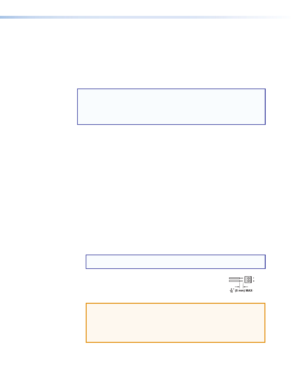
f
Power connector — Connect a 12 VDC power supply to this
3.5 mm, 2-pole direct insertion captive screw connector. Wire the
connector as shown at right.
ATTENTION: Potential damage to property.
•
Do not tin the wires. For best results and to reduce the risk of short circuits, trim
just 3/16 inch (5 mm) of the jacket from the wires.
•
Always use a power supply supplied by or specified by Extron. Use of an
unauthorized power supply voids all regulatory compliance certification and may
cause damage to the supply and the end product.
–
+
12
VD
C
Po
wer
Do not tin the wires!