Front panel features and cabling – Extron Electronics Extender Plus Series User Guide User Manual
Page 10
Extender Plus Series • Installation and Operation
4
•
If attaching the wall box to wood, use four #8 or #10 screws or 10-penny nails. A
minimum of ½ inch (1.3 cm) of screw threads must penetrate the wood.
•
If attaching the wall box to metal studs or furniture, use four #8 or #10 self-tapping
sheet metal screws or machine bolts with matching nuts.
8.
Set the gain switch, then cable and test the line driver before fastening the line driver
into the wall box. The switch and cables are not accessible after installation.
See “
Rear Panel Features and Cabling
” on page 5 for details.
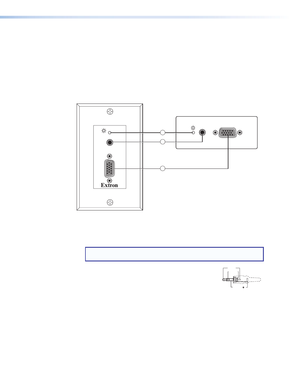
Front Panel Features and Cabling
AUDIO IN
COMPUTER IN
AUDIO IN
COMPUTER IN
EXTENDER Plus AAP
3
2
1
a
Power/signal LED — This LED lights:
•
Amber to indicate that the Extender is receiving power.
•
Green to indicate that an active signal with separate horizontal sync is present at
the input and the Extender is receiving power.
NOTE:
The LED remains lit amber when the input signal is HDTV component video,
RGsB, or RsGsBs.
b
Audio input connector — Plug a 3.5 mm stereo plug into this
jack for unbalanced audio input. Wire the male plug as shown at
right.
c
Computer In connector (RGB video) — Attach a cable
from the computer to the Extender via this female 15-pin HD
connector.
Sleeve ( )
Ring (R)
Tip (L)
3.5 mm Stereo Plug
Connector
(unbalanced)