Instant mute/unmute front panel controls, Diagnostic leds, Main menu – standard and customized – Extron Electronics Matrix 6400 Series User Manual
Page 16
Using the FPC 1000 Front Panel Controller • Chapter 3
Matrix 3200/6400 Series Switchers • FPC 1000 • User’s Manual • Extron
Instant Mute/Unmute Front Panel Controls
Instant RGB Mute/Unmute – This button allows all RGB video outputs to be muted
independent of any programmed muting. Press once and the LED lights to
indicate that all RGB outputs are muted. Press the button again to restore the
previous mute status. For example, if outputs 2, 29 and 35 were already muted,
turning this RGB Mute function Off will unmute all except those three outputs.
For muting of individual outputs from the panel see Page 3-11.
_______ Because RGB mute is done by switching off the RGB signal and leaving the sync
on, this button does not operate with composite or S-video system.
Instant Audio Mute/Unmute – This button allows all audio outputs to be muted
independent of any programmed muting. Press once and the LED lights to
indicate that all audio outputs are muted. Press the button again to restore the
previous mute status. That is, any audio outputs that were muted before will
remain muted. For muting of individual outputs from the panel see Page 3-11.
_______ The Audio button and LED will not operate if the system has no audio module.
Diagnostic LEDs
At the bottom of the BME front panel (below the FPC 1000 panel) there are
several LEDs that monitor the 3200/6400 switcher BME. These are explained in
the Matrix 3200/6400 Switcher manuals. The name and function of each LED is
as follows:
• Power Supplies – These four green LEDs indicate that the voltage is present. If
there is no second power supply, the two LEDs for “Redundant” will not be lit.
Primary +V
Primary -V
Redundant +V
Redundant -V
Figure 3-3. Diagnostic LEDs on the BME Front Panel
• Communications – The red LEDs indicate Tx (Transmit) and the green LEDs
indicate Rx (Receive) for three categories:
RS-232 – to show transmit/receive activity over the serial bus.
BME – to show communication activity between I/O modules (BMEs).
Remote – (not on Sync Modules) to show communication between remote
keypads or panels (MKP 1000 or MCP 1000) and the Master BME (module 0).
• The yellow Status LED indicates: On = normal; Off = there is an error.
Blinking = BME is busy communicating.
Main Menu – Standard and Customized
The Main menu, shown in Figure 3-1, displays the Extron logo, switcher model
and software version. This is the starting point for going to other menus. The
operation of this menu is described in the example on page 3-1. On power-up,
tests are made and the system status is checked and stored. During this period,
messages appear along the top of the screen that say: “Establishing
Communications” and then “Initializing” and then the menu titles appear.
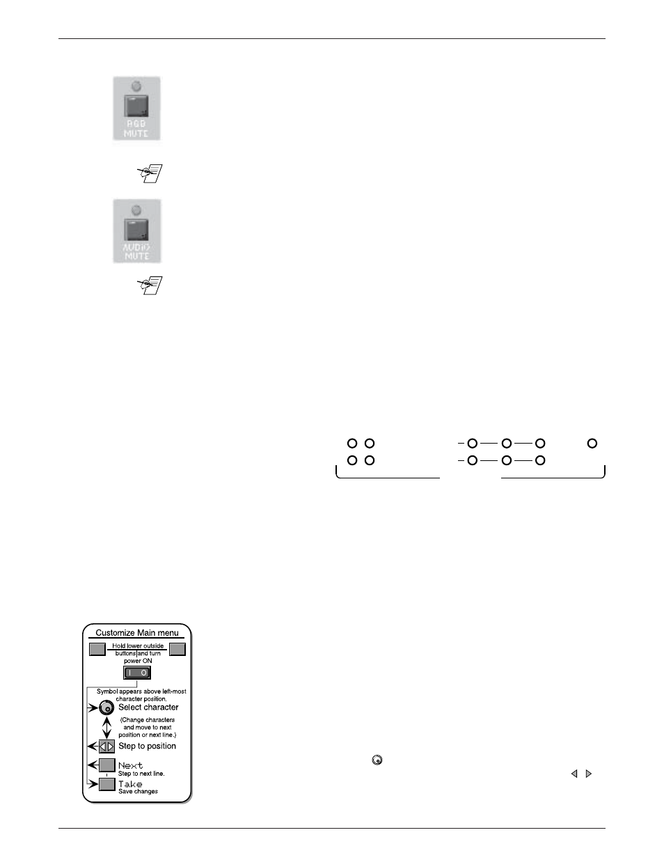
The bottom three lines of the main menu can be customized for the installation.
For example, it could be used to display information about the company
responsible for the system, a phone number, etc. (XYZ A/V Systems, Inc.)
To do this, hold the two bottom, corner buttons while turning power ON. (See
diagram left.) The knob symbol (
) acts as a cursor marking the character
position to be changed. Turn the knob to change that character. Use the (
)
buttons to move to another position and press the Next button to change lines.
Use the Caps button to change case. Press Take when finished editing the text.
3-3
POWER SUPPLIES
COMMUNICATIONS
PRIMARY
TX
RS232
BME
REMOTE
SYSTEM
STATUS
REDUNDANT
RX
DIAGNOSTICS
+V
-V