Application diagram, Figure 1. connection diagram for a dvc 501 sd, Dvc 501 sd • introduction 2 – Extron Electronics DVC 501 SD User Guide User Manual
Page 8
DVC 501 SD • Introduction
2
•
Analog RGB or component video output — Outputs analog RGB as RGBHV, RGBS,
or RGsB. Outputs component video as R-Y, B-Y, Y.
•
Buffered loop-through connector — A buffered input loop-through delivers reshaped
and restored multi-rate SDI signals.
•
Bi-level or tri-level sync is available for component video output.
•
Internal test patterns for calibration and setup — Nine test patterns are available,
including a crop pattern, color bars, and grayscale.
•
Muting control — Provides video and audio output muting.
•
RS-232 configuration and control — An RS-232 serial port provides configuration and
control via the Extron Simple Instruction Set (SIS™) commands.
•
USB configuration and control — A USB Config port provides configuration and
control via SIS commands.
•
Front panel security lockout — Locks out all front panel functions except for input
selection (all functions remain available through RS-232 or USB control).
•
Rack and furniture mountable 1U, half rack width metal enclosure
•
Internal universal power supply — The 100-240 VAC, 50-60 Hz, international power
supply provides worldwide power compatibility.
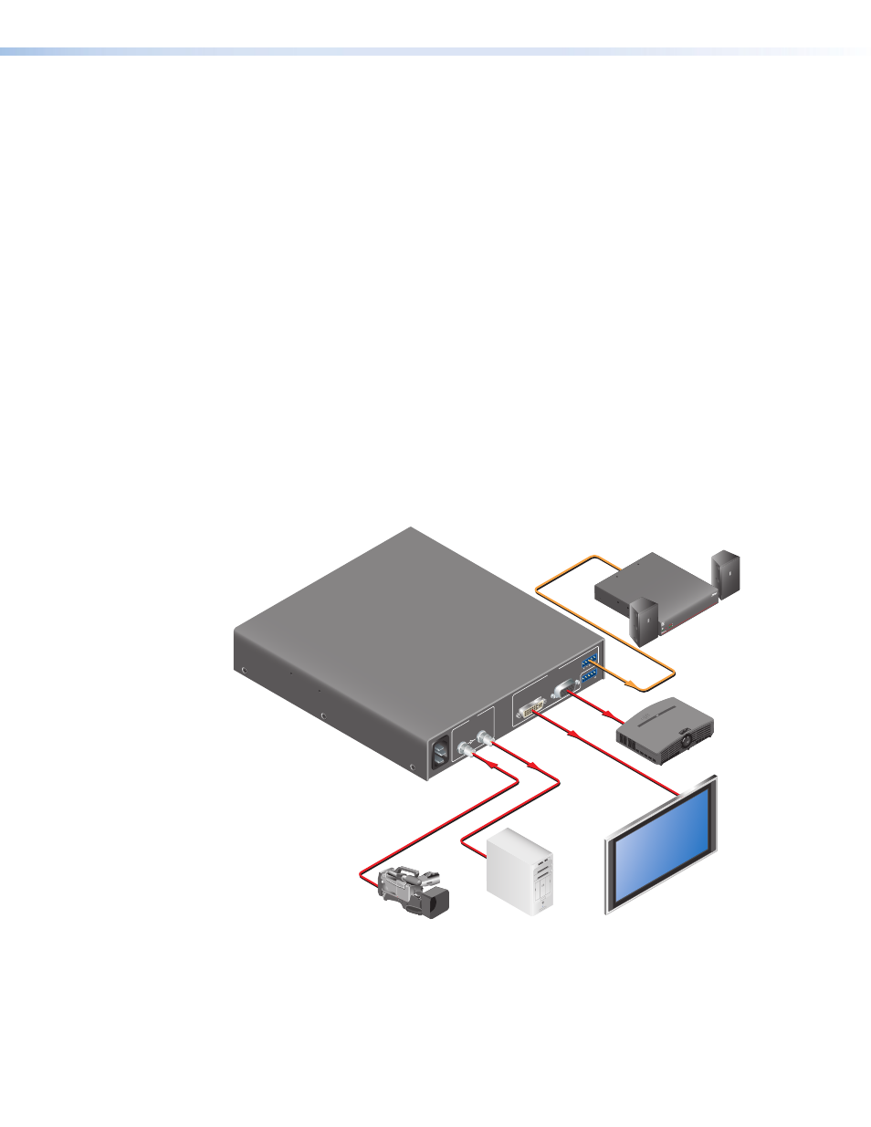
Application Diagram
The following diagram shows an example of a DVC 501 SD application.
100-240V ~ 0.5A
MAX
50/60 Hz
SDI / HD-SDI
BUFFERE
D
INPU
T
LOOP-THROUGH
RGB/R-
Y,Y
,B-
Y
OUTPU
T
DVI-
D
L
R
RS-232
N/A
Tx
Rx
AUDI
O
Extron
DVC 501 SD
SDI/HD-SDI to DVI and
RGB/YUV Converter
HDTV Camera
Video Capture
Flat Panel Display
HD Projector
Extron
XPA 1002
Power
Amplifier
Extron
SI 28
Surface-mount
Speakers
RGBHV
DVI
HD-SDI
HD-SDI
XP
A 1
002
1
2
LIMITER/PRO
TECT
SIGN
AL
OVER
TEMP
Figure 1.
Connection Diagram for a DVC 501 SD