Xylem FM500 ULTRASONIC FLOW METERS User Manual
Page 7
Page 7
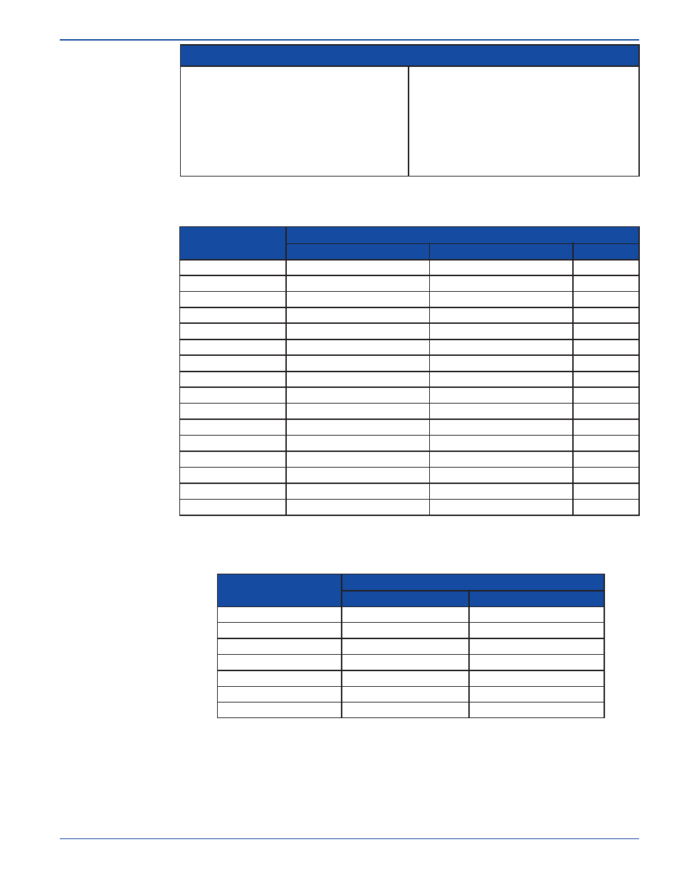
1.4
Fluid
Requirements
1.6
Straight Pipe
Length
Requirements
1.5
Pipe
Requirements
Doppler Operation
Transit Time Operation
!
!
0.02% to
15% (200 to 150,000 ppm)
Must conduct sound
Must contain sound reflecting particles such
as air bubbles, sand, etc.
Doppler measurement requires
particles be
present in the flow stream to “reflect” the
sound waves.
!
!
0% to
10% (0 to 100,000 ppm) of particles
Must conduct sound
Must be relatively clean fluid
Transit Time measurement requires relatively
“clean” fluid. Fluids containing from
are
acceptable.
Note: Do not attempt to measure very low flow velocities in the Doppler mode, the particles can fall out of
suspension resulting in error or failure.
Pipe Material
Pipe Size Ranges and Maximum Wall Thickness
Doppler Mode Pipe Size Range
Brass (Naval)
2“ to 100” (63mm to 2500mm)
Max Pipe Wall
Copper
FRP (fiberglass Reinforced Plastic)
.500” (13mm)
Iron (cast)
Iron (ductile)
Nylon
Polyethylene (HDPE)
Polypropylene
PVC / CPVC
304 Stainless Steel
Polyethylene (LDPE)
304L Stainless Steel
316 Stainless Steel
Steel (1% carbon hard)
Steel (carbon)
Titanium
Transit Time Mode Pipe Size Range
2“ to 100” (63mm to 2500mm)
2“ to 100” (63mm to 2500mm)
2“ to 100” (63mm to 2500mm)
2“ to 100” (63mm to 2500mm)
1“ to 100” (25mm to 2500mm)
1“ to 100” (25mm to 2500mm)
1“ to 100” (25mm to 2500mm)
1“ to 100” (25mm to 2500mm)
1“ to 100” (25mm to 2500mm)
2“ to 100” (63mm to 2500mm)
2“ to 100” (63mm to 2500mm)
2“ to 100” (63mm to 2500mm)
2“ to 100” (63mm to 2500mm)
2“ to 100” (63mm to 2500mm)
2“ to 100” (63mm to 2500mm)
2“ to 100” (63mm to 2500mm)
2“ to 100” (63mm to 2500mm)
2“ to 100” (63mm to 2500mm)
2“ to 100” (63mm to 2500mm)
2“ to 100” (63mm to 2500mm)
1-1/2“ to 100” (40mm to 2500mm)
2“ to 100” (63mm to 2500mm)
2“ to 100” (63mm to 2500mm)
2“ to 100” (63mm to 2500mm)
2“ to 100” (63mm to 2500mm)
2“ to 100” (63mm to 2500mm)
2“ to 100” (63mm to 2500mm)
.500” (13mm)
.500” (13mm)
.500” (13mm)
.500” (13mm)
.500” (13mm)
.500” (13mm)
.500” (13mm)
.500” (13mm)
.500” (13mm)
.500” (13mm)
2.00” (50mm)
2.00” (50mm)
2.00” (50mm)
1.00” (25mm)
.500” (13mm)
1-1/2“ to 100” (40mm to 2500mm)
1-1/2“ to 100” (40mm to 2500mm)
1-1/2“ to 100” (40mm to 2500mm)
1-1/2“ to 100” (40mm to 2500mm)
Note: The outside surface of the pipe must be clean and smooth. Insulation, coatings, rust and other surface
imperfections should be removed before installing the transducers. The inside surface of the pipe must be smooth to
properly reflect the sound wave.
Type of Disturbance
Straight Lengths of Pipe Required
Upstream from Transducers
Flange
5 x Nominal Pipe Size
Reducer
o
90 Elbow
Gate valve
Pump
Downstream from Transducers
o
Two 90 Elbows - 1 Direction
o
Two 90 Elbows - 2 Directions
5 x Nominal Pipe Size
7 x Nominal Pipe Size
5 x Nominal Pipe Size
10 x Nominal Pipe Size
5 x Nominal Pipe Size
15 x Nominal Pipe Size
5 x Nominal Pipe Size
20 x Nominal Pipe Size
5 x Nominal Pipe Size
25 x Nominal Pipe Size
5 x Nominal Pipe Size
25 x Nominal Pipe Size
5 x Nominal Pipe Size
Note: The sound wave beam is only affected by fluid that actually passes through the beam and therefore, the meter
will not measure with high accuracy if the fluid velocity is not consistent across the entire pipe diameter. Flow
disturbances such as pumps, elbows, tees, and valves in the flow stream can cause swirl patterns and vortices that
will affect the measurement. Install the transducers on a straight run of pipe as far as possible from any
disturbances. The distance required for high accuracy will depend on the type of disturbance.
Ultrasonic Flowmeter