0 overview of flowmeter operation, 1 power on and self-test, 2 description of operating states and controls – Xylem FM500 ULTRASONIC FLOW METERS User Manual
Page 20
Page 20
4.1
Power On
and
Self-Test
LCD DISPLAY
On application of power, the power LED (green) on the motherboard comes on and the
flowmeter performs self-test functions. The approximate duration of self-test is 10
seconds. The flowmeter indicates that it is in the Self-Test State as follows:
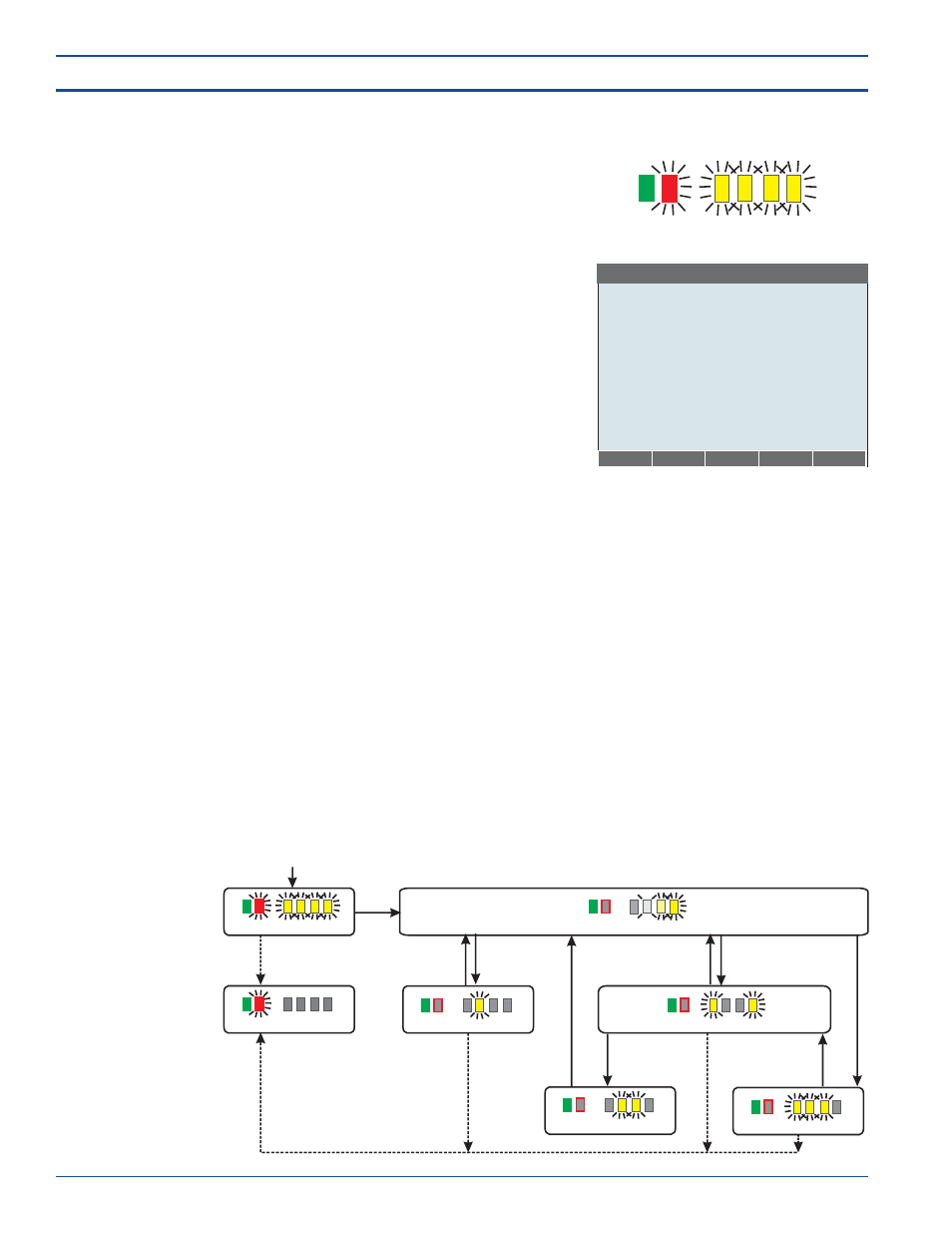
Below is a diagram of the flowmeter’s major operating states. The condition of the
motherboard LEDs is pictured under the name of each state. Transitions are annotated
with their causes, which may be user actions via the motherboard controls and timeouts
(uppercase text), user actions using a display optionally fitted to the flowmeter, (italic
text) or automatic transitions when a step is complete (in parentheses).
In the Self-Test state, the flowmeter checks the operation of internal circuitry, such as
communication between the processor and its peripheral functions, Verify that all LEDs
and the LCD display, if fitted, are working properly. Do not press any buttons during
self-test.
If an error condition is detected during self-test, the flowmeter enters the Faulted State.
Failure of the LEDs, LCD display, and the display touch-pad are not internally
detectable.
If self-test completes without error, the flowmeter enters the Startup State. Note that
completion of self-test does not guarantee that the flowmeter is properly configured and
able to make accurate measurements.
Model 1: the red and all four yellew LED
indicator lights flash at 1 Hz.
Model 2: as for Model 1, plus the LCD
shows the firmware version number and the
text “Self-Test ...”.
Model 3: as for Model 2.
INDICATOR LIGHTS IN
SELF-TEST STATE
Self-test …
Information Screen
Firmware Version, B01.00.00
TRANSDUCER POSITIONING
SELF-TEST
STARTUP STATE
ZERO CALIBRATION
RUN MODE
FAULTED STATE
SETUP MODE
Power ON
(fail)
(pass)
HOLD SETUP
FOR
3 SECONDS
(complete)
7 SECOND
TIME OUT
TAP SETUP BUTTON or
FLIP DOPPLER / TT
MODE SWITCH
TAP SETUP BUTTON or
TIME OUT (5 minutes) or
press “ESC” button
TAP SETUP
BUTTON
TAP SETUP
BUTTON or
Activate a
configuration
TAP SETUP
BUTTON or
press
“DONE” button
(fail)
(fail)
(fail)
SONIC-PRO OPERATING STATES
4.2
Description of
Operating
States and
Controls
4.0 Overview of Flowmeter Operation
Ultrasonic Flowmeter