0 transducer installation, 1 transducer piping system location, 2 transducer mounting mode for doppler measurement – Xylem FM500 ULTRASONIC FLOW METERS User Manual
Page 40
Page 40
6.1
Transducer
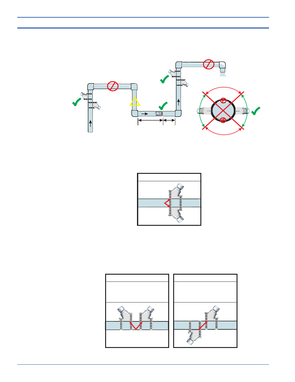
Piping System
Location
NO
NO
Air bubble
Sediment
OK
OK
OK
OK
NO
NO
Down flows
must have
back pressure
Pipe must be full
Air could be trapped
!
10 x D
5 x D
Flow
Direction
6.3
Transducer
Mounting
Mode for
Transit Time
Measurement
TRANSIT TIME MOUNTING MODES
DOPPLER MOUNTING MODE
All pipe types and sizes
Select a pipe location that provides a minimum straight length of pipe of at least 10
times the pipe’s nominal pipe size and mark a point that is at least 5 times the pipe
diameter downstream from the nearest pipe fitting. See section 1.6 for the minimum
straight pipe length requirements.
If the fluid to be measured contains particles, the meter should be operated using the
Doppler measurement method. For Doppler operation, the transducers will be mounted
directly opposite each other as shown below.
If the fluid contains little or no particles (up to 10% maximum), operate the meter using
the Transit Time method to obtain the best accuracy. Select “V” mounting mode when
possible. The “V” mounting mode allows the greatest sound travel distance while
permitting good signal strength. Basic pipe material and size general guidelines are
shown below.
TRANSDUCER MOUNTING LOCATION
6.0 Transducer Installation
6.2
Transducer
Mounting
Mode for
Doppler
Measurement
“V” Mount Mode
Typically smaller pipe sizes
from 2” to 6” diameter.
“Z” Mount Mode
Typically larger pipe sizes
from 4” to 100” diameter.
Ultrasonic Flowmeter