4 limit indicator, See section 4.5.4 – YSI IQ SensorNet DIQ/CR3 User Manual
Page 33
MIQ/CR3; DIQ/CR3
Settings
4 - 19
ba76032e01
01/2012
General
sensor errors
4.5.4
Limit indicator
Function
The characteristic of the limit indicator is laid down in the Limit value
UL, Limit value LL, Hysteresis UL and Hysteresis LL settings. The
fundamentals of the function are described in the introductory chapter
(see section 4.1.2).
In order to set up the Limit indicator function for a relay output, the relay
output must be linked with a sensor (see section 4.3).
Settings
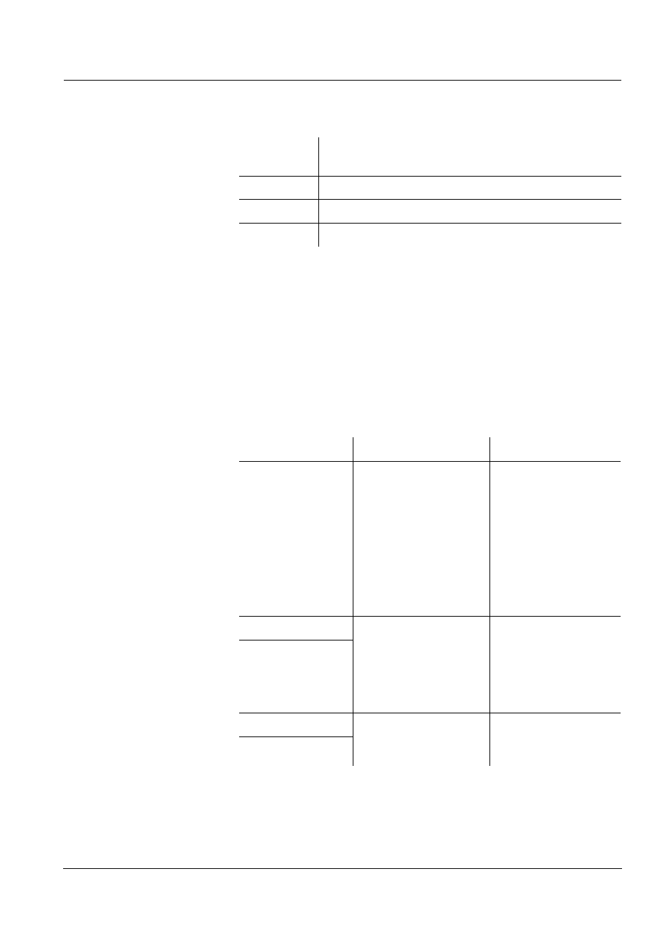
Init
can prompt a relay action for a short time, depending
on the starting behavior of the system
----
Invalid measured value, or defective sensor
Error
Communication with sensor interrupted
OFL
Measuring range undercut or exceeded (overflow)
Setting
Selection/Values
Explanation
Limit values
UL main variable
LL main variable
UL adjoining var.
LL adjoining var.
Main variable
designates the actual
measured parameter
of the sensor (e.g.
pH, oxygen, etc.).
Adjoining variable
designates an
additional measured
parameter (e.g.
temperature).
Limit value UL
Any upper and lower
limiting value
within the measuring
range (sensor-
dependent)
Minimum spacing
between the upper
and lower limiting
value:
5 % of the measuring
range
Limit value LL
Hysteresis UL
0 - 5% of the
measuring range
Hysteresis for Limit
value UL and Limit
value LL.
Hysteresis LL