Asus A7N8X Deluxe User Manual
Page 40
26
Chapter 2: Hardware information
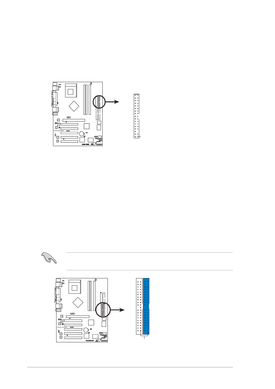
9) Floppy Disk Drive Connector (34-1 pin FLOPPY)
This connector supports the provided floppy drive ribbon cable. After
connecting the single end to the board, connect the two plugs on the other
end to the floppy drives. (Pin 5 is removed to prevent inserting in the
wrong orientation when using ribbon cables with pin 5 plugged).
A7N8X
®
NOTE: Orient the red markings on
the floppy ribbon cable to
PIN 1
A7N8X Floppy Disk Drive Connector
PIN 1
FLOPPY1
10) Primary (Blue) / Secondary (Black) IDE Connectors
(40-1 pin PRI_IDE1 and SEC_IDE1)
The Primary and Secondary IDE connectors support the IDE hard disk ribbon
cables supplied with the motherboard. Connect the cable’s blue connector
to the motherboard’s primary IDE connector (recommended) or the secondary
IDE connector. Connect the opposite end of the cable to your UltraDMA133/
100/66 device (hard disk drive). If a second hard disk drive is connected,
youmay reset its jumper to Slave or Master/Slave mode. Non-UltraDMA133/
100/66 devices should be connected to the secondary IDE connector. BIOS
supports specific device bootup (see 4.4.1 Advanced BIOS Features).
IMPORTANT!
UltraDMA133 IDE devices require a 40-pin 80-conductor
cable and RAID arrays only operate with such cables.
A7N8X
®
A7N8X IDE Connectors
NOTE: Orient the red markings
(usually zigzag) on the IDE
ribbon cable to PIN 1.
SEC_IDE1
PIN 1
PRI_IDE1