Hardware setup – Asus MES-N User Manual
Page 34
34
ASUS MES-N User’s Manual
Connectors
3. H/W SETUP
3. HARDWARE SETUP
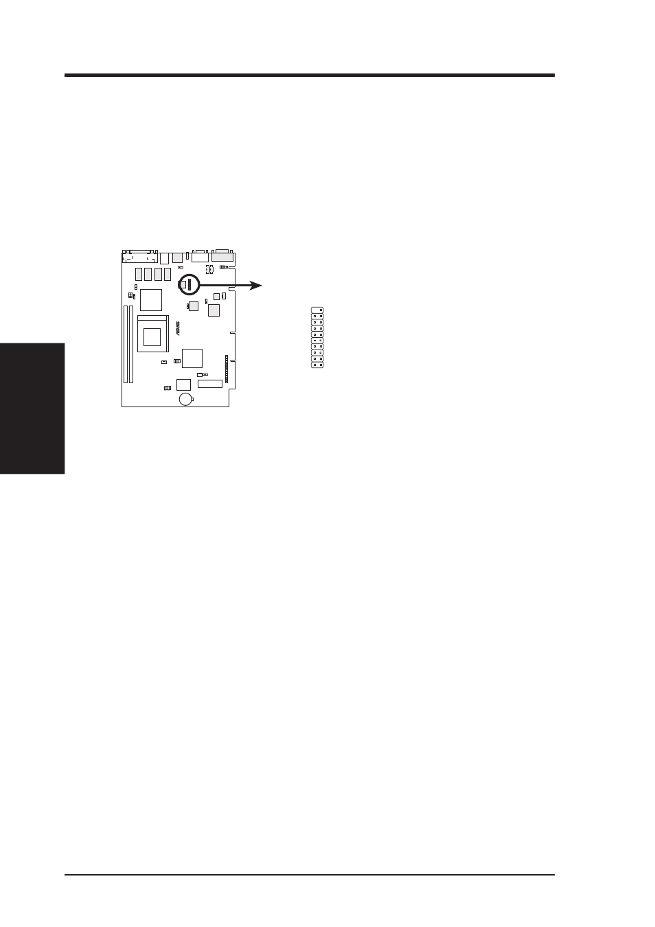
5) LCD Header (20-1 pin LCDHD)
This header requires a digital LCD cable connector. Connect the digital LCD
cable to the LCD header and mount the bracket to the chassis on a free expan-
sion slot. NOTE: If both CRT and digital LCD monitors are used, the CRT will
take precedence. This header is for a digital LCD panel; an analog LCD panel
comes with a 15-pin VGA cable connector to be used on the monitor connector.
NOTE: This connector is available only on motherboards with optional Digital
Flat Panel (DFP) interface support.
®
TOP:
MOUSE
BOTTOM:
KEYBOARD
MES-N
MES-N LCD Header
LCDHD
1
11
10
20
20: (No pin)
19: (No connection)
18: TX2+
17: GND
16: TX1-
15: TX0+
14: GND
13: TXC-
12: +5V
11: FDDCDAT
10: (No connection)
9: GND
8: TX2-
7: TX1+
6: GND
5: TX0-
4: TXC+
3: GND
2: PLSENSE
1: FDDCCLK
- P5B Premium Vista Edition (188 pages)
- P5B (140 pages)
- P5B (56 pages)
- P5KPL-VM/1394/SI (94 pages)
- M2N68-CM (28 pages)
- P5GD1-VM (92 pages)
- P5AD2-E Premium (2 pages)
- P5GD1-VM (88 pages)
- P5AD2 Premium (8 pages)
- DELUXE A7N8X-E (114 pages)
- P5KPL-AM SE (40 pages)
- P5KPL-AM SE (38 pages)
- P5KPL-AM SE (62 pages)
- P4S8X-X (64 pages)
- P5K-VM (98 pages)
- K8V-X SE (82 pages)
- M2N68-AM SE2 (40 pages)
- P4P800 SE (125 pages)
- P4P800 SE (16 pages)
- DELUXE SERIES M3A32-MVP (176 pages)
- P5AD2 Deluxe (148 pages)
- M4A79 Deluxe (122 pages)
- A7V266-E (108 pages)
- Application Manual (1 page)
- Application Manual (5 pages)
- Application Manual (11 pages)
- Application Manual (10 pages)
- Application Manual (4 pages)
- Application Manual (8 pages)
- Application Manual (2 pages)
- Application Manual (6 pages)
- Application Manual (9 pages)
- Application Manual (3 pages)
- M4A88T-I DELUXE (70 pages)
- M4A88T-I DELUXE (44 pages)
- P9X79 DELUXE (2 pages)
- RAMPAGE IV GENE (1 page)
- P9X79 (156 pages)
- P8H61-M PLUS V3 (64 pages)
- A85XM-A (78 pages)
- M4A78L-M LE (64 pages)
- M2N68-AM (96 pages)
- M2N68-AM (62 pages)
- M2N68-AM (38 pages)
- Blitz Formula (3 pages)