Hardware setup, 1 tr-dls motherboard layout, 14 asus tr-dls user’s manual – Asus TR-DL User Manual
Page 14: Motherboard layout 3. h/w setup
14
ASUS TR-DLS User’s Manual
3. HARDWARE SETUP
3.1
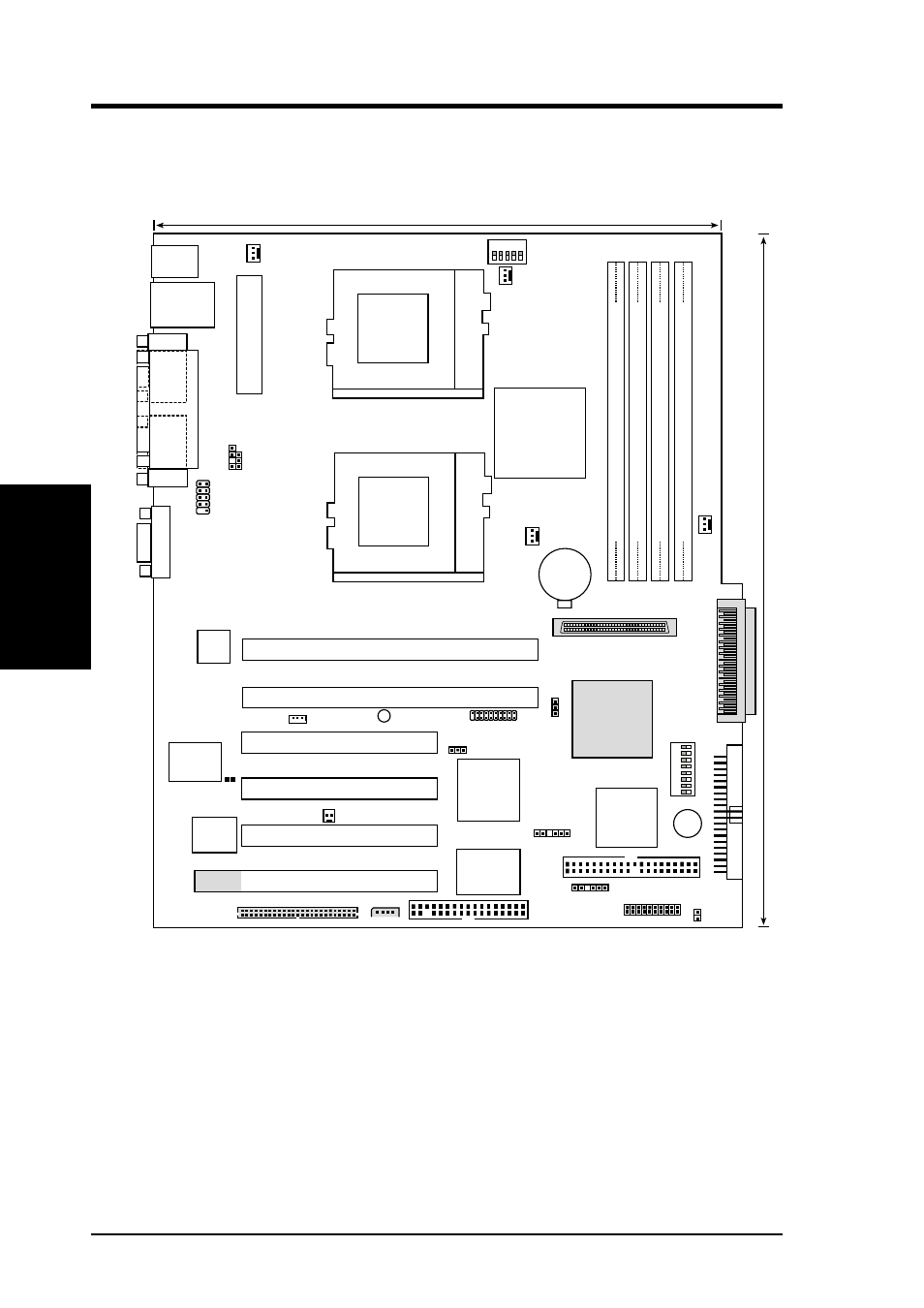
TR-DLS Motherboard Layout
Motherboard Layout
3. H/W SETUP
Primary IDE1
Secondary IDE2
FLOPPY
ASUS
ASIC
with Hardware
Monitor
CHASSIS
4Mbit
Flash
BIOS
WOL_CON
TR-DLS
PCI3 (32-bit, 33MHz 5V)
PCI1 (64-bit, 66MHz 3V)
A
TX_POWER
CHA_FAN1
CPU_FAN1
PANEL
HD_LED
Intel
Fast
Ethernet
ATI
RAGE XL
VGA
Controller
LSI
SCSI
Controller
CONFIG
USBPORT
Digital Flat Panel
(DFP) Connector
WOR
68-Pin Ultra160/Ultra2-Wide
SCSI Connector
SCSI-A
BPSMB
CHA_F
AN2
35
68
34
1
24.4cm (9.6in)
30.5cm (12in)
PGA
370
PGA
370
DIMM Socket 0 (72-bit, 168-pin module)
0 1
DIMM Socket 1 (72-bit, 168-pin module)
2 3
DIMM Socket 2 (72-bit, 168-pin module)
4 5
DIMM Socket 3 (72-bit, 168-pin module)
6 7
PS/2
T: Mouse
B: Keyboard
Top:
RJ-45
Bottom:
USB1
USB2
COM1
P
ARALLEL
PORT
COM2
VGA
PCI2 (64-bit, 66MHz 3V)
PCI4 (32-bit, 33MHz 5V)
PCI5 (32-bit, 33MHz 5V)
CR2032 3V
Lithium Cell
CMOS Power
1234
5678
KBPWR
BPSMB
68-Pin Ultra160/Ultra2-Wide
SCSI Connector
SCSI-B
LED1
CPU_FAN2
SCSIEN
CLKSW
1 2 3 4 5
VGAEN
BUZZER
eRMC CONNECTOR
IPMI
PCI6 (32-bit, 33MHz 5V)
CLRCMOS
ServerWorks
RCC
LE-T
North Bridge
®
ServerWorks
RCC
CSB5
South Bridge
®
Super
I/O
NOTE: The SCSI and ASMC features, eRMC connector, and IPMI
connectors are optional components. These are grayed out in the above
motherboard layout.