Iii. installation, P/i-p55tp4n user's manual – Asus P/I-P55TP4N User Manual
Page 30
P/I-P55TP4N User's Manual
24
III. INSTALLATION
(Connectors)
III. INST
ALLA
TION
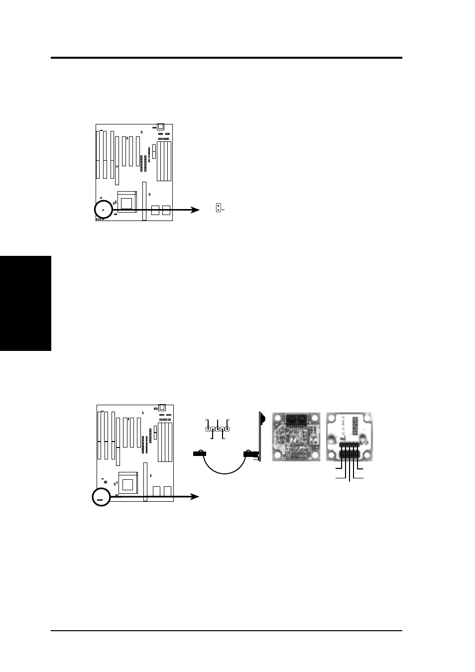
14. IDE activity LED (JP17)
This connector connects to the hard disk activity indicator light on the
case.
IDE (Hard Drive) LED
JP17
+
16. IrDA-compliant infrared module connector (JP31)
This connector supports the optional wireless transmitting and receiv-
ing infrared module. This module mounts to a small opening on sys-
tem cases that support this feature. You must also configure the setting
through BIOS setup on page 36 to select whether UART2 is directed
for use with COM2 or IrDA. Use the five pins (as defined by Intel) as
shown on the Back View and connect a ribbon cable from the module
to the motherboard according to the pin definitions. The ribbon cable
that may be supplied may either have five or ten pins (for other stan-
dards). If using a ten-pin ribbon cable, use only the top five row of the
ribbon cable plug.
Infrared Module Connector (JP31)
Front View
+5V
IRTX
IRRX
NC
GND
Back View
IRRX
+5V
IRTX
NC
GND
- P5B (56 pages)
- P5B Premium Vista Edition (188 pages)
- P5B (140 pages)
- P5KPL-VM/1394/SI (94 pages)
- M2N68-CM (28 pages)
- P5AD2 Premium (8 pages)
- P5GD1-VM (92 pages)
- P5AD2-E Premium (2 pages)
- P5GD1-VM (88 pages)
- DELUXE A7N8X-E (114 pages)
- P5KPL-AM SE (40 pages)
- P5KPL-AM SE (38 pages)
- P5KPL-AM SE (62 pages)
- P4S8X-X (64 pages)
- P5K-VM (98 pages)
- K8V-X SE (82 pages)
- M2N68-AM SE2 (40 pages)
- P4P800 SE (125 pages)
- P4P800 SE (16 pages)
- DELUXE SERIES M3A32-MVP (176 pages)
- P5AD2 Deluxe (148 pages)
- M4A79 Deluxe (122 pages)
- A7V266-E (108 pages)
- Application Manual (3 pages)
- Application Manual (1 page)
- Application Manual (5 pages)
- Application Manual (11 pages)
- Application Manual (10 pages)
- Application Manual (4 pages)
- Application Manual (8 pages)
- Application Manual (2 pages)
- Application Manual (6 pages)
- Application Manual (9 pages)
- M4A88T-I DELUXE (70 pages)
- M4A88T-I DELUXE (44 pages)
- P9X79 (156 pages)
- P9X79 DELUXE (2 pages)
- RAMPAGE IV GENE (1 page)
- P8H61-M PLUS V3 (64 pages)
- A85XM-A (78 pages)
- M4A78L-M LE (64 pages)
- M2N68-AM (96 pages)
- M2N68-AM (62 pages)
- M2N68-AM (38 pages)
- Blitz Extreme (188 pages)