Iii. installation, 72 pin dram in simm socket – Asus P/I-P55TP4N User Manual
Page 19
P/I-P55TP4N User's Manual
13
III. INSTALLATION
(DRAM Memory)
III. INST
ALLA
TION
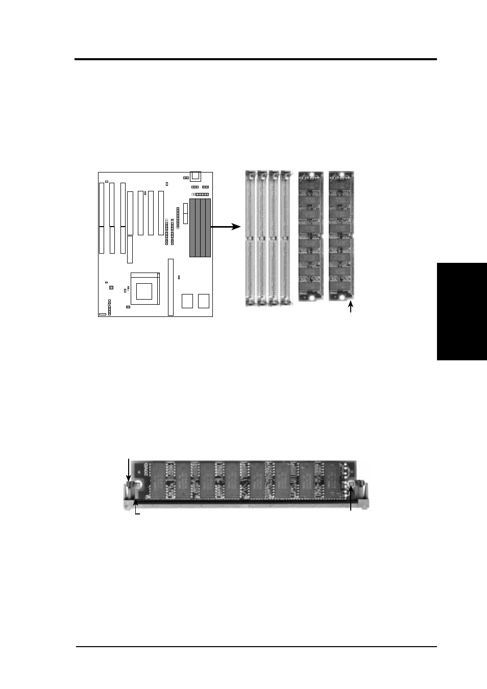
DRAM Memory Installation Procedures:
1. The SIMM memory modules will only fit in one orientation as shown
because of a "Plastic Safety Tab" on one end of the SIMM slots which
requires the "Notched End" of the SIMM memory modules.
72 Pin SIMM DRAM Slots & Module
1
2
3
4
Notched End
2. Press the memory module firmly into place starting from a 45 degree
angle making sure that all the contacts are aligned with the slot.
3. With your finger tips, rock the memory module into a vertical position
so that it clicks into place.
Metal Clip
Plastic Safety Tab (This Side Only)
Mounting Hole
72 Pin DRAM in SIMM Socket
4. The plastic guides should go through the two "Mounting Holes" on the
sides and the "Metal Clips" should snap on the other side.
5. To release the memory module, squeeze both "Metal Clips" outwards
and rock the module out of the "Metal Clips".
- P5B Premium Vista Edition (188 pages)
- P5B (140 pages)
- P5B (56 pages)
- P5KPL-VM/1394/SI (94 pages)
- M2N68-CM (28 pages)
- P5GD1-VM (88 pages)
- P5AD2 Premium (8 pages)
- P5GD1-VM (92 pages)
- P5AD2-E Premium (2 pages)
- DELUXE A7N8X-E (114 pages)
- P5KPL-AM SE (40 pages)
- P5KPL-AM SE (38 pages)
- P5KPL-AM SE (62 pages)
- P4S8X-X (64 pages)
- P5K-VM (98 pages)
- K8V-X SE (82 pages)
- M2N68-AM SE2 (40 pages)
- P4P800 SE (125 pages)
- P4P800 SE (16 pages)
- DELUXE SERIES M3A32-MVP (176 pages)
- P5AD2 Deluxe (148 pages)
- M4A79 Deluxe (122 pages)
- A7V266-E (108 pages)
- Application Manual (8 pages)
- Application Manual (2 pages)
- Application Manual (6 pages)
- Application Manual (9 pages)
- Application Manual (3 pages)
- Application Manual (1 page)
- Application Manual (5 pages)
- Application Manual (11 pages)
- Application Manual (10 pages)
- Application Manual (4 pages)
- M4A88T-I DELUXE (70 pages)
- M4A88T-I DELUXE (44 pages)
- RAMPAGE IV GENE (1 page)
- P9X79 (156 pages)
- P9X79 DELUXE (2 pages)
- P8H61-M PLUS V3 (64 pages)
- A85XM-A (78 pages)
- M4A78L-M LE (64 pages)
- M2N68-AM (62 pages)
- M2N68-AM (38 pages)
- M2N68-AM (96 pages)
- Blitz Extreme (188 pages)