Iii. installation – Asus P/I-P55TP4N User Manual
Page 26
P/I-P55TP4N User's Manual
20
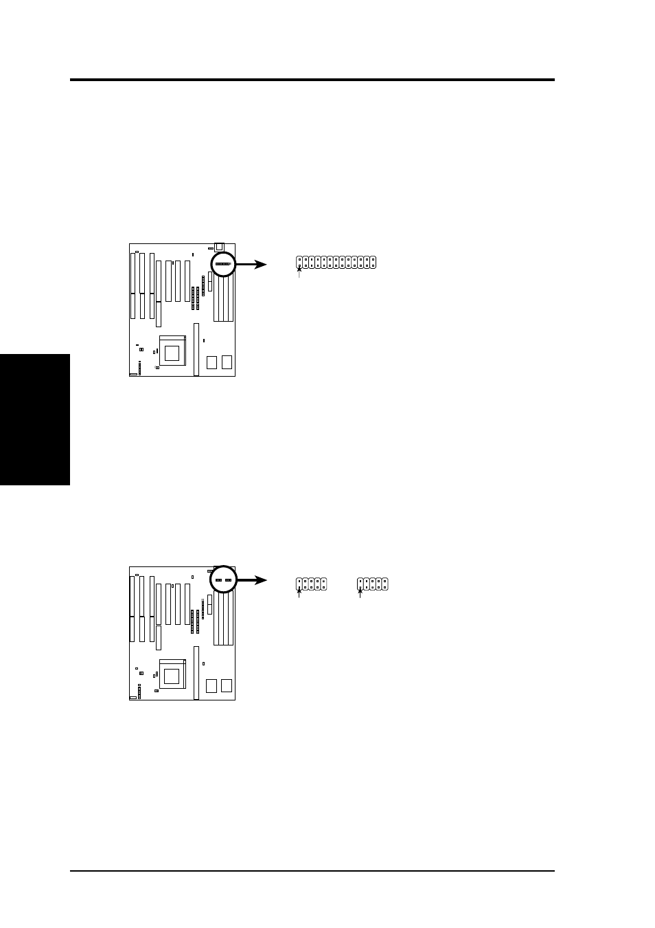
3. Parallel Printer Connector (26 Pin Block)
Connection for the included parallel port ribbon cable with mounting
bracket. Connect the ribbon cable to this connection and mount the
bracket to the case on an open slot. It will then be available for a
parallel printer cable. Note: Serial printers must be connected to the
serial port. You can enable the parallel port and choose the IRQ through
BIOS Setup on page 35 "Onboard Parallel Port."
Parallel (Printer) Connector
Pin 1
4. Serial port COM1 and COM2 connectors (Two 10-pin blocks)
These connectors support the provided serial port ribbon cables with
mounting bracket. Connect the ribbon cables to these connectors and
mount the bracket to the case on an open slot. The two serial ports on
the mounting bracket will then be used for pointing devices or other
serial devices. See page 35 for BIOS configuration of "Onboard Serial
Port"
COM 1
COM 2
Pin 1
Pin 1
Serial Port Connectors
III. INSTALLATION
(Connectors)
III. INST
ALLA
TION
- P5B Premium Vista Edition (188 pages)
- P5B (140 pages)
- P5B (56 pages)
- M2N68-CM (28 pages)
- P5KPL-VM/1394/SI (94 pages)
- P5GD1-VM (92 pages)
- P5AD2-E Premium (2 pages)
- P5GD1-VM (88 pages)
- P5AD2 Premium (8 pages)
- DELUXE A7N8X-E (114 pages)
- P5KPL-AM SE (38 pages)
- P5KPL-AM SE (62 pages)
- P5KPL-AM SE (40 pages)
- P4S8X-X (64 pages)
- P5K-VM (98 pages)
- K8V-X SE (82 pages)
- M2N68-AM SE2 (40 pages)
- P4P800 SE (125 pages)
- P4P800 SE (16 pages)
- DELUXE SERIES M3A32-MVP (176 pages)
- P5AD2 Deluxe (148 pages)
- M4A79 Deluxe (122 pages)
- A7V266-E (108 pages)
- Application Manual (10 pages)
- Application Manual (4 pages)
- Application Manual (8 pages)
- Application Manual (2 pages)
- Application Manual (6 pages)
- Application Manual (9 pages)
- Application Manual (3 pages)
- Application Manual (1 page)
- Application Manual (5 pages)
- Application Manual (11 pages)
- M4A88T-I DELUXE (70 pages)
- M4A88T-I DELUXE (44 pages)
- P9X79 DELUXE (2 pages)
- RAMPAGE IV GENE (1 page)
- P9X79 (156 pages)
- P8H61-M PLUS V3 (64 pages)
- A85XM-A (78 pages)
- M4A78L-M LE (64 pages)
- M2N68-AM (96 pages)
- M2N68-AM (62 pages)
- M2N68-AM (38 pages)
- Blitz Extreme (1 page)