Asus ESC4000 G2 User Manual
Page 49
2-27
ASUS ESC4000 G2 Series
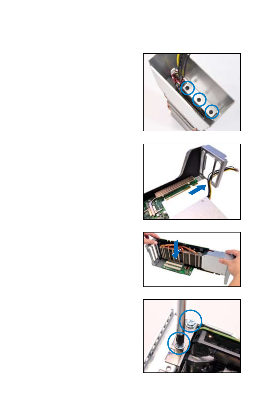
6. Thread the white end of the 8-
pin power cable through the GPU
computing module bracket.
7. Align and insert the golden fingers
of the GPU computing module into
the card slot on the bracket. Ensure
the card is completely seated on the
slot.
8. Secure the rear end of the GPU
computing module to the bracket with
two screws.
5. From inside the airduct, secure
the airduct to the GPU computing
module with 3 black screws.
This manual is related to the following products:
See also other documents in the category Asus Computer hardware:
- AP2500 (40 pages)
- AP1700-S5 (58 pages)
- RS700-E6/ERS4 (138 pages)
- AP1600R-E2(AA2) (150 pages)
- P7F-E (162 pages)
- RS161-E4/PA2 (126 pages)
- RS163-E4/RX4 (11 pages)
- M2N-LR (113 pages)
- P5BV/SAS (184 pages)
- K8N-DRE (142 pages)
- RS161-E5/PA2 (124 pages)
- LSI SAS3442X-R (68 pages)
- PIKE 2208 (16 pages)
- ESC4000 (162 pages)
- ESC4000 (22 pages)
- PSCH-SR/IDE (102 pages)
- P9D-M (156 pages)
- RS740-E7-RS24-EG (212 pages)
- P5M2-E/4L (12 pages)
- ESC2000 G2 (226 pages)
- TS700-E6/RS8 (166 pages)
- RS160-E3/PS4 (140 pages)
- PU-DLS (134 pages)
- TR-DLSR (100 pages)
- P5BV-C/2L (161 pages)
- TS100-E5/PI4 (166 pages)
- ESC1000 Personal SuperComputer (184 pages)
- NRL-LS (120 pages)
- PCI-DA2200 (369 pages)
- P8C WS (140 pages)
- RS120-E4/PA4 (174 pages)
- P5MT-M (150 pages)
- TS Mini (112 pages)
- TS Mini (114 pages)
- TS Mini (2 pages)
- P5MT-MX/C (156 pages)
- AP140R-E1 (52 pages)
- AP140R-E1 (132 pages)
- ASMB6-iKVM (114 pages)
- DSBF-D16/SAS (200 pages)
- DSBF-D16 (202 pages)
- RS160-E5 (164 pages)
- Z8PE-D12X (170 pages)
- Z8PE-D12X (168 pages)