GE Industrial Solutions KS24194 Power Wire User Manual
Page 2
2
Lineage Power
Data Sheet
KS-24194™ Power Wire
March 2010
KS-24194 Class B Stranded Conductor Specifications, List 3
Wire Size
AWG or
kCMil
Area
(CMil)
(Nom.)
Current
Capacity
(Amps)
1
Cond.
Dia.
(in)
Max dc
Resistance
2
Min Bend
Radius
(in)
3
No. of
Strands
Dia. of
Strand
Const.
4
Avg. Insul.
Thickness
(in)
List 3
Dimeter
(in)
List 3
Weight /
1000 ft (lb)
Max Ship
Length
per Reel
14
4110
25
0.073
2.730
1
7
0.071
0.045
0.197
30
20,000
12
6530
30
0.092
1.720
1
7
0.089
0.045
0.216
43
20,000
10
10,380
40
0.116
1.080
1-1/4
7
0.113
0.045
0.247
58
15,000
8
16,510
55
0.146
0.678
1-1/2
7
0.142
0.060
0.308
91
10,000
6
26,250
75
0.184
0.427
1-3/4
7
0.178
0.060
0.346
130
6000
4
41,740
95
0.232
0.269
2
7
0.225
0.060
0.394
189
4500
2
66,360
130
0.292
0.169
2-1/4
7
0.283
0.060
0.454
279
3000
1/0
105,500
170
0.373
0.106
2-7/8
19
0.362
0.080
0.577
438
2000
2/0
133,100
195
0.419
0.084
3-1/8
19
0.405
0.080
0.622
534
1500
4/0
211,600
260
0.528
0.052
3-5/8
19
0.512
0.080
0.730
806
1000
350
350000
350
0.681
0.032
4-5/8
37
0.661
0.095
0.922
1301
700
500
500,000
430
0.813
0.022
5-3/8
37
0.789
0.095
1.052
1804
500
750
750,000
535
0.998
0.0148
6-3/8
61
0.968
0.110
1.265
2669
350
1. Ampacities shown here are based on not more than three single, insulated conductors in a raceway with a 30 °C ambient
temperature. (Follow the National Electrical Code Article 310 Type RHH Correction Factors.)
2. In Ohms/1000 ft. at 20 °C.
3. Minimum bend radius is equal to five times the overall wire diameter.
4. Minimum diameter compressed stranded construction.
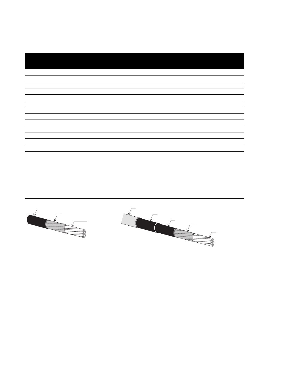
Outline Drawings
INSULATION
INSULATION
SEPARATOR
SEPARATOR
SEPARATOR
COTTON BRAID
CONDUCTOR
(CLASS I
STRANDING)
CONDUCTOR
(CLASS B
STRANDING)
Typical KS-24194 List 2 Power Wire
Typical KS-24194 List 3 Power Wire