GE Industrial Solutions SG Series 10 – 20 – 30 – 40 kVA Installation Guide User Manual
Page 31
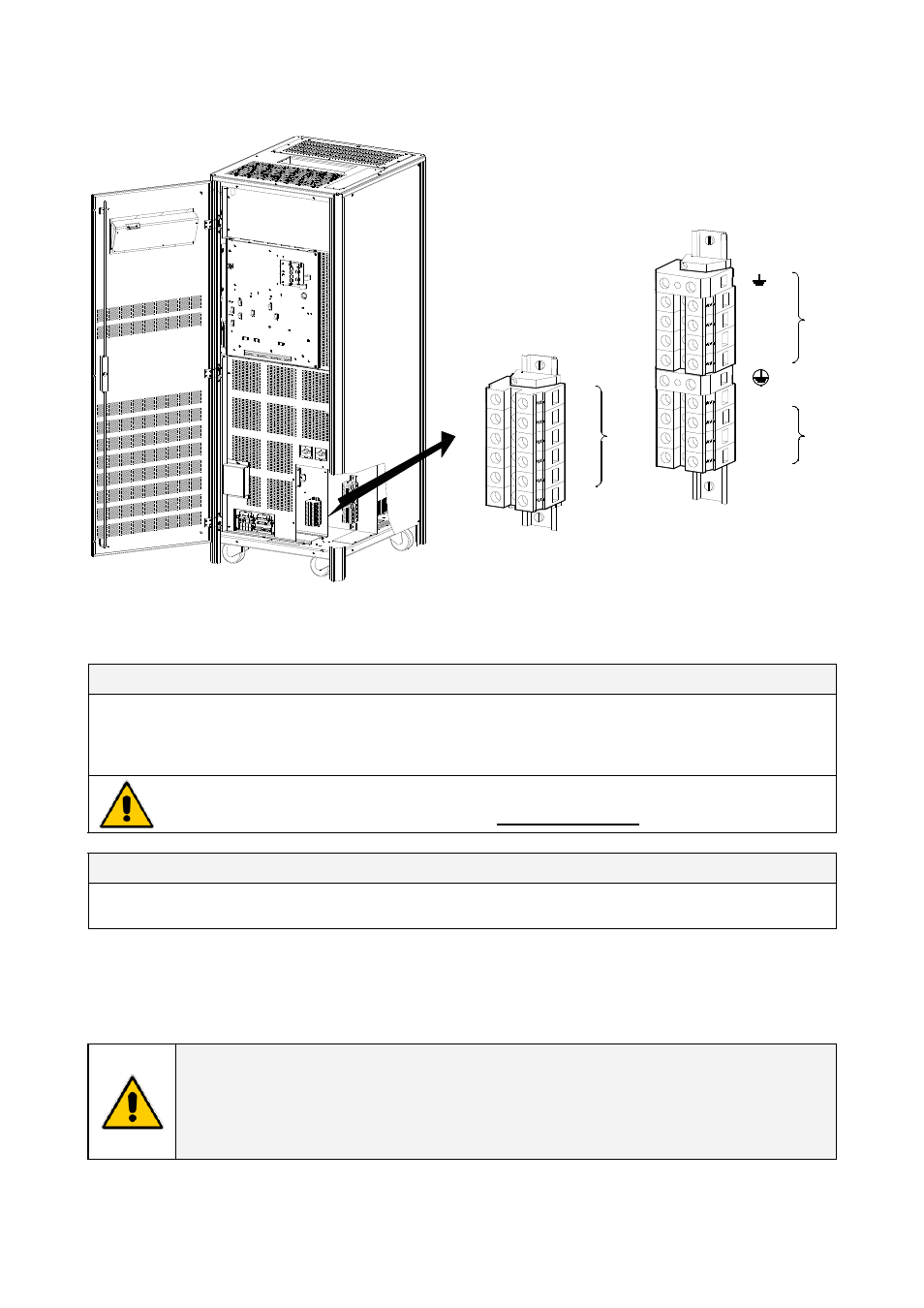
3.8.5 Power connection dual input utility of SG Series 30 & 40 kVA
L1-1
X1
L1
PE
PE
S
G
T
50
00
_03
0-
0
40_
UP
S
c
onnection separ
ate
_01US
L2
L3
N
L2-1
L3-1
N - Bypass
OFF
ON
OFF
ON
2- IN
PU
T B
YP
ASS
L1-2
L2-2
L3-2
X2
L3
L2
L1
RECT
IF
IE
R
1 - INP
U
T
L
OAD
Fig. 3.8.5-1 Power connections Dual Input Utility of SG Series 30 & 40 kVA
SG Series 30 & 40 kVA Max.
rating
X1 and X2 terminals:
1 AWG (50mm
2
)
Dual Input Configuration Rectifier / Bypass
L1-1
Rectifier Phase A
L1-2
Bypass Phase A
L2-1
Rectifier Phase B
L2-2
Bypass Phase B
L3-1
Rectifier Phase C
L3-2
Bypass Phase C
PE
N - Bypass
Bypass Neutral
Ground
For dual input configurations, a neutral conductor is required from the bypass source only.
The interconnection links BR1, BR2 and BR3 MUST BE REMOVED (see Fig. 3.8.5-2).
Output Load
L1
Load Phase A
L2
Load Phase B
L3
Load Phase C
N
PE
Load Neutral
Load Ground
Cable terminations are to the Rectifier / Bypass Input Terminals and Load Output Terminals as shown
above.
Connect wire to the Terminals using appropriate tools and appropriate torque.
Torque specification for Input / Output and DC power connections on Terminals: see Section 3.8.1.
NOTE !
This UPS is only designed to operate in a wye-configured electrical system with a
solidly grounded neutral.
If the UPS is equipped with an input transformer, the secondary of the transformer
must be wye-configured with neutral solidly grounded.
Modifications reserved
Page 31/45
OPM_SGS_ISG_10K_40K_0US_V040.doc
Installation Guide SG Series 10 –20 – 30 - 40 kVA