Ac b d – GE Industrial Solutions SG Series 400 & 500 Installation Guide User Manual
Page 23
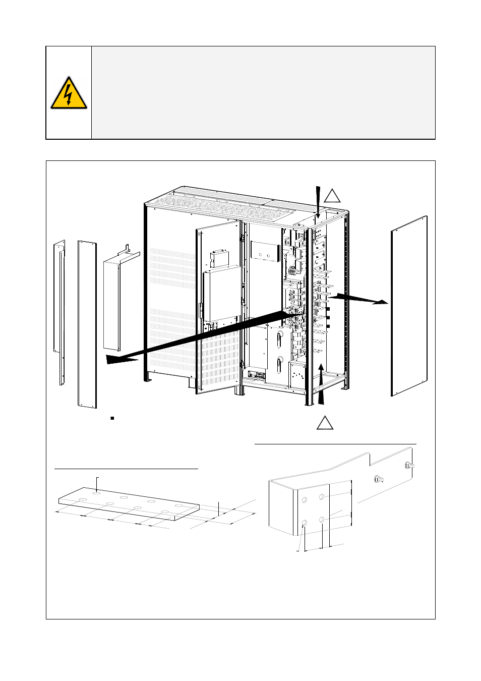
CAUTION !
Panel “A, B, C and D” should never be removed or replaced with power applied to the
UPS.
This panel is in close proximity to 480V live buss bars.
Always disconnect the rectifier, bypass, load and battery sources from the UPS
before removing or replacing this panel.
If not serious injury or death could occur!
Access to power wiring terminals for the cable connections.
Q1
0 OFF
I O
N
Q2
0 OFF
I O
N
SGSU_400-500_S2
_UPS connection_0
1US
Bottom entry cables
Please remove the plate
before drilling any holes
!
Please remove the plate
before drilling any holes
!
Detail of the power wiring terminal for the AC input/output
Detail of the power wiring terminal for external battery connection
2"
51mm
0.57
"
14.5
mm
2"
51mm
2"
51mm
1.02"
26mm
Ø 0.55" / 14mm
Ø 0.55" / 14mm
1.75"
44.5mm
0.57
"
14.5
mm
31.5
"
80m
m
1.75"
44.5mm
0.79"
20mm
1.97" 50mm
0.98" 25
m
m
0.98" 25
m
m
A
C
B
D
Top entry cables
) Dual mains customer connection bars are optional
) Manual Bypass switch is optional
*
*
Fig. 3.8.1-1 Access to the input / output connections
To access input, output and Battery Connections proceed as follows:
• Remove the protection panel “A, B and C”.
• Remove the UPS side panel “D”.
Modifications reserved
Page 23/41
OPM_SGS_ISG_M40_M50_2US_V021.doc
User Manual SG Series 400 & 500 UL S2