Data sheet, Feature descriptions – GE Industrial Solutions QBVS050A0B Barracuda Series User Manual
Page 8
GE
Data Sheet
QBVS050A0B Barracuda Series; DC-DC Converter Power Modules
52-60Vdc Input; 12.0Vdc, 50.0A, 600W Output
October 31, 2013
©2012 General Electric Company. All rights reserved.
Page 8
Feature Descriptions
Overcurrent Protection
To provide protection in a fault output overload condition,
the module is equipped with internal current-limiting
circuitry and can endure current limiting continuously. If the
overcurrent condition causes the output voltage to fall
greater than 3.0V from V
o,set
, the module will shut down and
remain latched off. The overcurrent latch is reset by either
cycling the input power or by toggling the on/off pin for one
second. If the output overload condition still exists when the
module restarts, it will shut down again. This operation will
continue indefinitely until the overcurrent condition is
corrected.
A factory configured auto-restart option (with overcurrent
and overvoltage auto-restart managed as a group) is also
available. An auto-restart feature continually attempts to
restore the operation until fault condition is cleared.
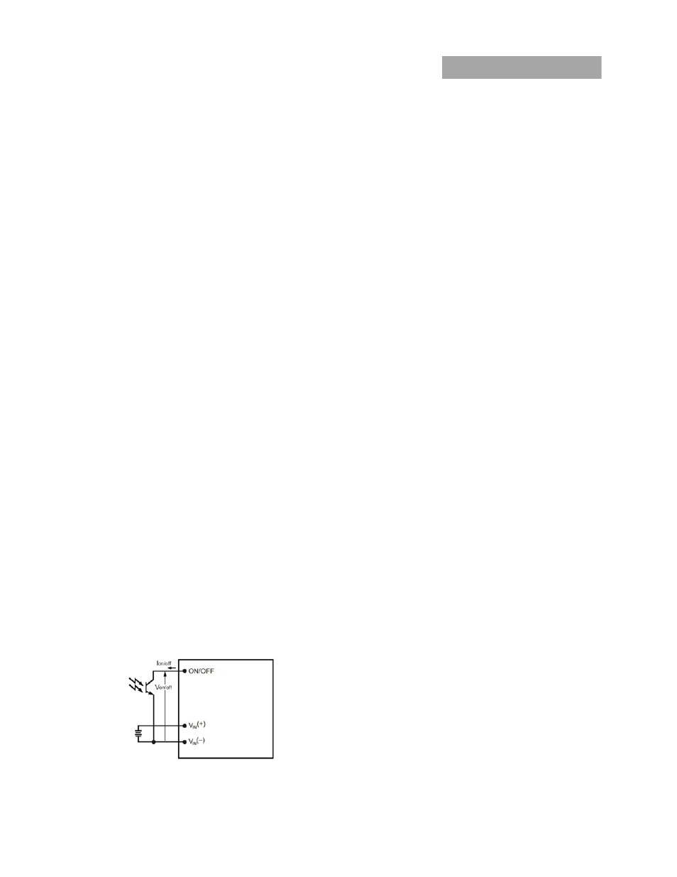
Remote On/Off
The module contains a standard on/off control circuit
reference to the V
IN
(-) terminal. Two factory configured
remote on/off logic options are available. Positive logic
remote on/off turns the module on during a logic-high
voltage on the ON/OFF pin, and off during a logic low.
Negative logic remote on/off turns the module off during a
logic high, and on during a logic low. Negative logic, device
code suffix "1," is the factory-preferred configuration. The
On/Off circuit is powered from an internal bias supply,
derived from the input voltage terminals. To turn the power
module on and off, the user must supply a switch to control
the voltage between the On/Off terminal and the V
IN
(-)
terminal (V
on/off
). The switch can be an open collector or
equivalent (see Figure 12). A logic low is V
on/off
= -0.3V to 0.8V.
The typical I
on/off
during a logic low (Vin=48V, On/Off
Terminal=0.3V) is 147µA. The switch should maintain a logic-
low voltage while sinking 200µA. During a logic high, the
maximum V
on/off
generated by the power module is 8.2V. The
maximum allowable leakage current of the switch at V
on/off
=
2.4V is 130µA. If using an external voltage source, the
maximum voltage V
on/off
on the pin is 14.5V with respect to
the V
IN
(-) terminal.
If not using the remote on/off feature, perform one of the
following to turn the unit on:
For negative logic, short ON/OFF pin to V
IN
(-).
For positive logic: leave ON/OFF pin open.
Figure 12. Remote On/Off Implementation.
Output Overvoltage Protection
The module contains circuitry to detect and respond to
output overvoltage conditions. If the overvoltage condition
causes the output voltage to rise above the limit in the
Specifications Table, the module will shut down and remain
latched off. The overvoltage latch is reset by either cycling
the input power, or by toggling the on/off pin for one
second. If the output overvoltage condition still exists when
the module restarts, it will shut down again. This operation
will continue indefinitely until the overvoltage condition is
corrected.
A factory configured auto-restart option (with overcurrent
and overvoltage auto-restart managed as a group) is also
available. An auto-restart feature continually attempts to
restore the operation until fault condition is cleared.
Overtemperature Protection
These modules feature an overtemperature protection
circuit to safeguard against thermal damage. The circuit
shuts down the module when the maximum device
reference temperature is exceeded. The module will
automatically restart once the reference temperature cools
by ~25°C.
Input Under/Over voltage Lockout
At input voltages above or below the input under/over
voltage lockout limits, module operation is disabled. The
module will begin to operate when the input voltage level
changes to within the under and overvoltage lockout limits.
Thermal Considerations
The power modules operate in a variety of thermal
environments and sufficient cooling should be provided to
help ensure reliable operation.
Thermal considerations include ambient temperature,
airflow, module power dissipation, and the need for
increased reliability. A reduction in the operating
temperature of the module will result in an increase in
reliability. The thermal data presented here is based on
physical measurements taken in a wind tunnel.
Heat-dissipating components are mounted on the top side
of the module. Heat is removed by conduction, convection
and radiation to the surrounding environment. Proper
cooling can be verified by measuring the thermal reference
temperature (TH
1
).
Peak temperature occurs at the position indicated in Figure
16. For reliable operation this temperature should not
exceed TH
1
=100°C. For extremely high reliability you can
limit this temperature to a lower value. The output power of
the module should not exceed the rated power for the
module as listed in the Ordering Information table.