GE Industrial Solutions SG Series 50 & 80 kVA Operating Manual User Manual
Page 23
Modifications reserved
Page 23/82
OPM_SGS_USM_50K_80K_0US_V030.doc
Operating Manual SG Series 50 & 80 kVA
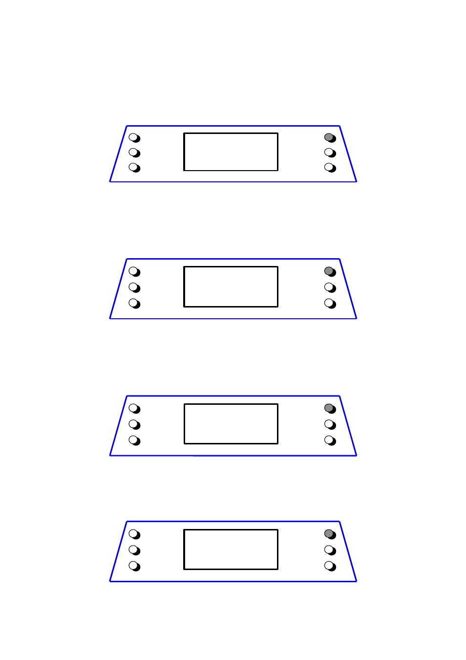
Rectifier Utility data screen
This screen refers to the AC source supplying the Rectifier.
This screen displays:
• Iout1 = output current Rectifier Bridge.
• Iout2 = output current 2
nd
Rectifier Bridge (optional 12 pulse Rectifiers only).
• The voltage levels between the three phases (line-to-line).
• The input frequency of the Rectifier.
R EC TIFIER
U 12=481V
Iout1
=107A
U 23=480V
Iout2
=
0A
U 31=482V
f=60.0H z
m etering
alarm s
param eters
+
–
ok
Inverter data screen
This screen displays:
• The voltage level of the three phase voltages (line-to-neutral).
• The output frequency of the Inverter.
• The synchronization status of the Inverter with respect to Utility.
INVERTER: U1=277V
U2= 277V
U3=277V
Frequency = 60.0Hz
Synchronized
metering
alarms
parameters
+
–
ok
Status Load screen
This screen displays:
• The Load level in kVA (for RPA: only this unit).
• The Load level as a percentage of the nominal rated Load (for RPA: only this unit).
• The source of the power supplied to the Load.
LOAD ON UPS
Load =
62.05kVA
Percentage = 77%
LOAD ON INVERTER
metering
alarms
parameters
+
–
ok
Load on phases screen 1
This screen displays for each phase:
• The output phase voltage and current as RMS values (for RPA: total value of Parallel System).
• The output Load as percent (for RPA: respect to the rated power of Parallel System).
LOAD ON PHASES
U1=277V I=81A 84%
U2=277V I=70A 73%
U3=277V I=73A 76%
metering
alarms
parameters
+
–
ok