GE Industrial Solutions QS873A Thermal Probe Kit User Manual
Title, Change history, Name: date: revision: description of change
Doc ID:
CC848817445-MAN
1 OF 3
3/31/2008
Doc Type:
General Manual
11:14:34 AM
Doc Issue:
See change history above
Lineage Power
Proprietary - Use Pursuant To Company Instructions
Title:
CC848817445: Instructions for QS873A Thermal Probe Expansion Kit
(For use with Kit CC109135027: 3EM21240AA)
Change History:
Name:
Date:
Revision: Description Of Change
KAL
1/24/2007
1
INITIAL RELEASE
KAL
3/28/2007
2
REPLACE 848719811 WITH CC848822321 (RoHS EQUIVALENT)
PDS
3/31/08
3
Lineage Power Version
Required Tools:
Wrench required to loosen/tighten hardware on battery posts. The size of this wrench is dictated by the batteries.
Procedure:
1. Verify all material is in kit.
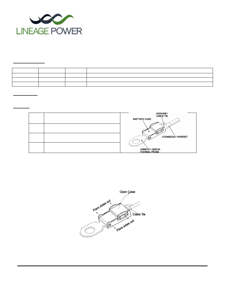
Qty 1
108987611 QS873A Thermal Probe Assembly
Qty 1
CC848822321 Wireset (Pre-attached to
Thermal Probe)
Qty 1
402244081 Cable Tie (Attached)
Qty 2
848715074 Case (1 Attached & 1 Loose Spare)
2. Select the last thermal probe in the existing thermal probe daisy chain. This is the probe where the Thermal Probe Expansion
Kit will connect. If this existing probe can be disconnected from its battery during installation of the expansion kit, this will
make the process easier.
3. On the existing thermal probe, cut the cable tie (strain relief) and open the case (if case is damaged during opening, a spare is
provided in the expansion kit). Do not unplug existing wireset. See Figure 1.
FIGURE 1: Opening Thermal Probe Case