Thermal considerations without baseplate – GE Industrial Solutions QPW050-060 Series User Manual
Page 15
Data Sheet
February 2, 2011
QPW050/060 Series Power Modules; DC-DC converters
36-75Vdc Input; 1.2Vdc to 3.3Vdc Output
LINEAGE
POWER
15
Thermal Considerations without
Baseplate
The power modules operate in a variety of thermal
environments; however, sufficient cooling should be
provided to help ensure reliable operation.
Considerations include ambient temperature, airflow,
module power dissipation, and the need for increased
reliability. A reduction in the operating temperature of
the module will result in an increase in reliability. The
thermal data presented here is based on physical
measurements taken in a wind tunnel.
Heat-dissipating components are mounted on the top
side of the module. Heat is removed by conduction,
convection and radiation to the surrounding
environment. Proper cooling can be verified by
measuring the thermal reference
temperature (T
ref
).
Peak temperature (T
ref
) occurs at the position
indicated in Figures 38 - 40. For reliable operation this
temperature should not exceed listed temperature
threshold.
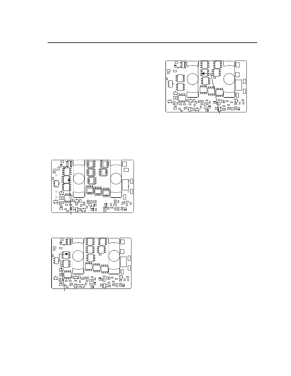
Figure 38.
T
ref
Temperature Measurement
Location for V
o
= 3.3V – 2.5V.
Figure 39.
T
ref
Temperature Measurement
Location for V
o
= 1.8V.
Figure 40. T
ref
Temperature Measurement
Location for V
o
= 1.5V – 1.2V
The output power of the module should not exceed
the rated power for the module as listed in the
Ordering Information table.
Although the maximum Tref temperature of the power
modules is 110 °C - 115 °C, you can limit this
temperature to a lower value for extremely high
reliability.
Heat Transfer via Convection
Increased airflow over the module enhances the heat
transfer via convection. Following derating figures
shows the maximum output current that can be
delivered by each module in the respective orientation
without exceeding the maximum T
ref
temperature
versus local ambient temperature (T
A
) for natural
convection through 2m/s (400 ft./min).
Note that the natural convection condition was
measured at 0.05 m/s to 0.1 m/s (10ft./min. to 20
ft./min.); however, systems in which these power
modules may be used typically generate natural
convection airflow rates of 0.3 m/s (60 ft./min.) due to
other heat dissipating components in the system. The
use of Figures 41 - 50 are shown in the following
example:
Example
What is the minimum airflow necessary for a
QPW050A0F operating at VI = 48 V, an output
current of 30A, and a maximum ambient temperature
of 70 °C in longitudinal orientation.
Solution:
Given: VI = 48V
Io = 30A
TA = 70 °C
Determine airflow (V) (Use Figure 41):
V = 1m/sec. (200ft./min.)
T
ref
=110ºC
T
ref
=115ºC
T
ref
= 115ºC