Bay extenders, Sample order, Documentation – GE Industrial Solutions Micro-BDCBB User Manual
Page 20: Table 3-e: recommended single hole terminal lugs, For terminating to circuit breakers, Table 3-f: bay extenders
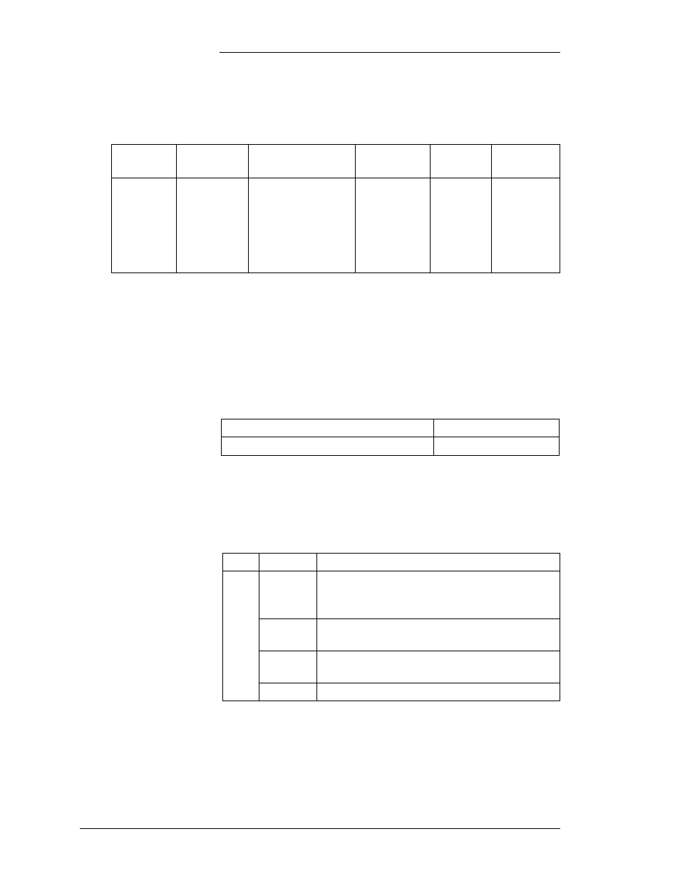
Table 3-E: Recommended Single Hole Terminal Lugs
for Terminating to Circuit Breakers
KS-5482
Wire
KS-20921
Wire
Terminal
Lug
Comcode
Die
Mounting
Material
10
8
6
4
2
-
10
8
6
4
-
2
WP-91412 L94
WP-91412 L74
WP-91412 L2
WP-91412 L4
WP-91412 L53
WP-91412 L7
406338152
405356189
405347436
405347543
405348186
405347659
WT-1300
Red
Blue
Grey
Brown
Green
Furnished
With
Panel
J85568E-1 Secondary DC Mini-Distribution Bay
3 - 4 Ordering Information
Issue 6 January 2008
Bay Extenders
Table 3-F gives the ordering information for the 2
′and 4′-6″ bay
extenders. These are used when the Mini-Distribution Bay is
installed in a 7
′ framework that is located in a 9′ or 11′-6″
environment. (Note: Do not mount Mini-Distribution Bay
onto bay extenders.)
Table 3-F: Bay Extenders
2
′ extender for 9′ environment
ED8C804-50 G3
4
′-6″ extender for 11′-6″ environment ED8C804-50 G5
Sample Order
An order for a Mini-Distribution Bay containing two fuse
panels, two blank panels and mounted in a framework would
look like this:
Item Quantity
Description
1
1
J85568E-1 List 2 -48V Mini-Distribution
Bay
equipped with:
2
List C Fuse Panels
Pnl Pos 1, 3
2
List B Blank Panels
Pnl Pos 2, 4
1
List A Framework
Documentation
The following documentation is associated with the
Mini-Distribution Bay: