Neutral current sensor connection – GE Industrial Solutions TKH-TKL with MicroVersaTrip Plus User Manual
Page 4
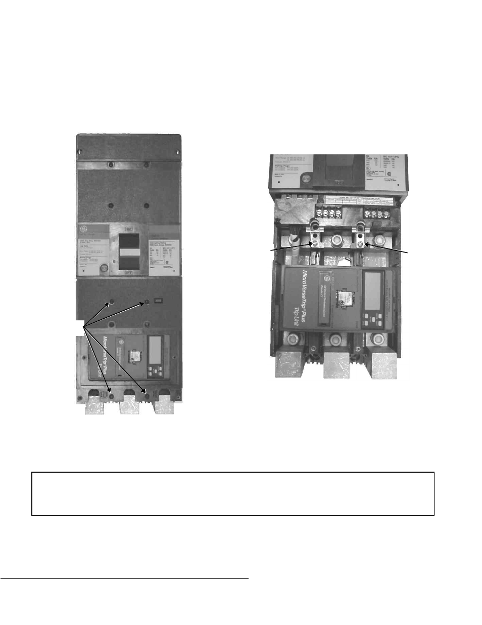
Neutral Current Sensor
Connection
A neutral current sensor must be used for ground-fault
protection on all single-phase, three-wire systems and
three-phase, four-wire systems.
1 . Remove the two screws that hold the lug cover in
place, then remove the lug cover.
2 . Remove the four screws that hold the lower part of
the breaker cover in place.
3 . Lift off the lower part of the breaker cover.
4 . Attach the leads of the current sensor to the
terminations shown in the illustration. The vertical
surfaces of the terminals closest to the trip unit are
labeled
BLACK
and
WHITE
on the left and right sides
of the breaker, respectively. Maintain the proper
polarity by connecting the black wire to the black
connector and the white wire to the white connector.
Use #14 AWG (minimum) twisted-pair insulated
conductors.
5 . File break-out locations in the bottom cover with a
circular file. Route the ground-fault leads out the
bottom cover, being careful not to pinch the leads.
6 . Replace the breaker cover, then replace the lug
cover, attaching both with the fasteners removed in
steps 1 and 2. Tighten the screws to 14–20 in-lb.
g
GE Industrial Systems
General Electric Company
41 Woodford Ave., Plainville, CT 06062
GEH5374 R02 1000
© 2000 General Electric Company
These instructions do not cover all details or variations in equipment nor do they provide for every possible contingency that
may be met in connection with installation, operation, or maintenance. Should further information be desired or should
particular problems arise that are not covered sufficiently for the purchaser’s purposes, the matter should be referred to the
GE Company.
Cover
Screws
Black
Terminal
White
Terminal