Ground-fault sensor connection – GE Industrial Solutions Spectra Series Power Panelboards ANK Neutrals (Model 2) User Manual
Page 2
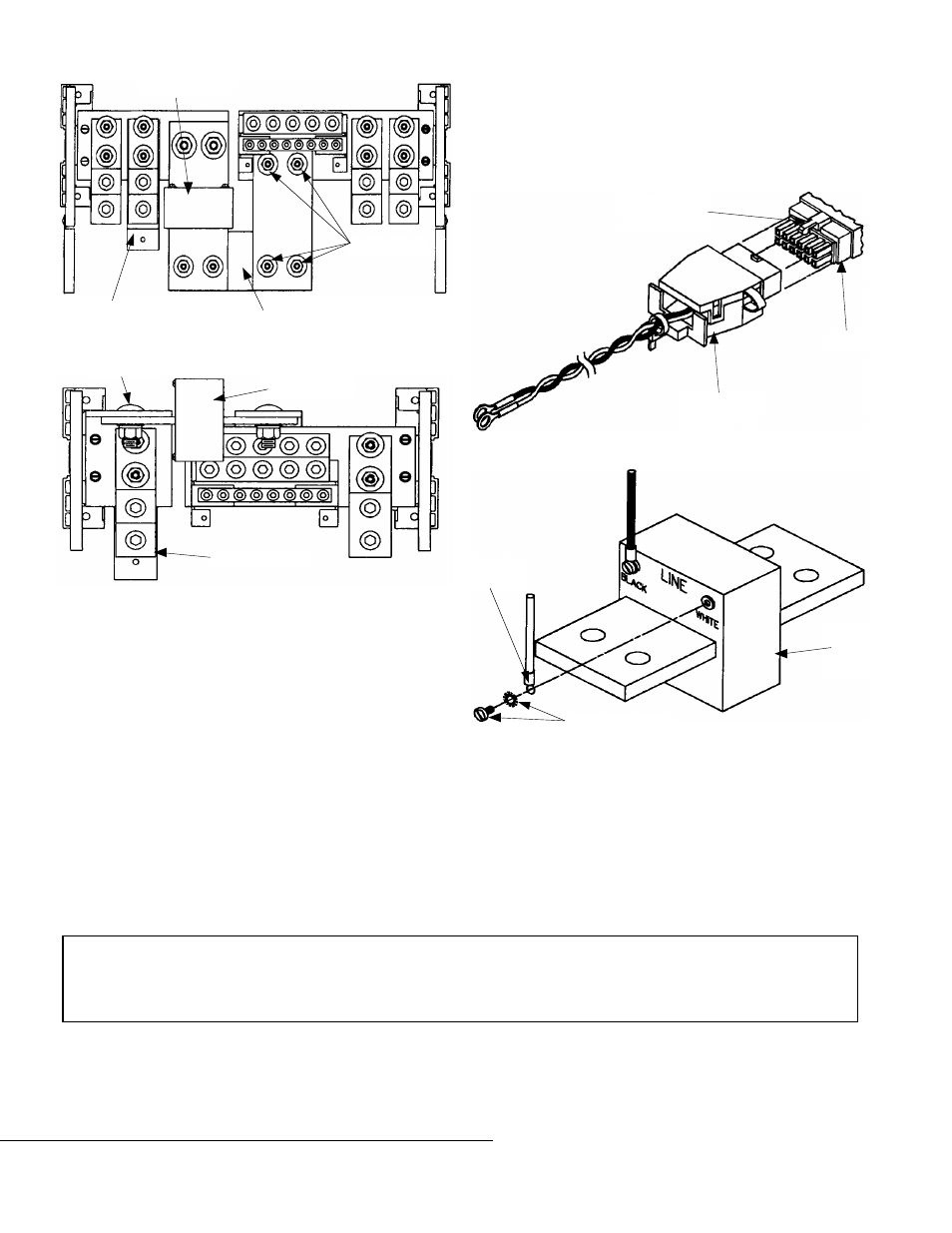
Figure 4. 800–1200 A neutral with ground-fault sensor.
Figure 5. 400–600 A neutral with ground-fault sensor.
Ground-Fault Sensor Connection
The ground fault wires are in one of two configurations
depending on the circuit breaker type. One has the wires exiting
the circuit breaker and ending at the ring terminals; go to step
8. The other requires a connection of the receptacle and the
plug, which are keyed for ease of installation; follow steps 6 to
8.
6. Align the connector receptacle and the plug, as shown in
Figure 6. Mate the plug with the receptacle by pushing
them together until the plug retention clip locks into the
receptacle.
7. Run the ground fault sensor connector wires through to the
neutral ground-fault sensor assembly.
8. Connect the black wire to the ground-fault sensor terminal
labeled
BLACK
. Connect the white wire to the ground fault
sensor terminal labeled
WHITE
. Secure the ring terminal
with the star washer and pan head screw, as shown in
Figure 7.
Figure 6. Attaching the connector receptacle and plug.
Figure 7. Attaching the wires to the ground-fault sensor.
g
GE Industrial Systems
General Electric Company
41 Woodford Ave., Plainville, CT 06062
GEH5585 R05 0401
© 2001 General Electric Company
These instructions do not cover all details or variations in equipment nor do they provide for every possible contingency that
may be met in connection with installation, operation, or maintenance. Should further information be desired or should
particular problems arise that are not covered sufficiently for the purchaser’s purposes, the matter should be referred to the
GE Company.
Ground-Fault
Sensor
Bonding Strap
Connector Strap
3
/
8
-16 Nuts
3
/
8
-16 Bolt
Ground-Fault
Sensor
Bonding Strap
Connector
Receptacle
Plug
Retention Clip
Plug
Ground-
Fault
Sensor
Screw & Washer
Ring
Terminal