GE Industrial Solutions Spectra Series Power Panelboards ANK Neutrals (Model 2) User Manual
Spectra series™ power panelboards, Installation, Type ank neutrals (model 2)
g
Spectra Series™ Power Panelboards
Type ANK Neutrals (Model 2)
Installation
WARNING: Danger of electrical shock or injury.
Turn
OFF power ahead of the panelboard or
switchboard before working inside the equipment or
removing any component
.
Equipment is to be
installed and maintained by properly trained and
qualified personnel only.
1. Mount the neutral at either location in the end of the
panelboard enclosure marked
NEUTRAL
on the
1
/
4
-20
mounting studs, as shown in Figure 1. Secure with the flat
washer, lock washer, and nut provided and tighten to
27–32 in-lb.
Figure 1. Mounting locations on the panelboard enclosure.
Figure 2. Securing the neutral to the panelboard.
2. Fasten the opposite end of the neutral to the enclosure
with two 10-32 x
11
/
16
" thread-forming screws provided.
Tighten to 27–32 in-lb. Figure 3 shows the neutral
mounted to the back wall of the enclosure.
Figure 3. Neutral mounted to the back wall of the enclosure.
3. When a bonding strap is required for service entrance
applications, first loosen the wire connector nuts at the
positions indicated in Figure 3. Slide the bond strap
provided with the neutral under the connector, then
retighten the nuts to 200–250 in-lb.
NOTE: If the box is painted, scratch through the paint in the
area where the bonding strap is in contact with the enclosure.
4. Secure the bond strap to the enclosure with the 10-32 x
3
/
8
" SEMS screw provided. Tighten to 27–32 in-lb. The
installation of the neutral is now complete.
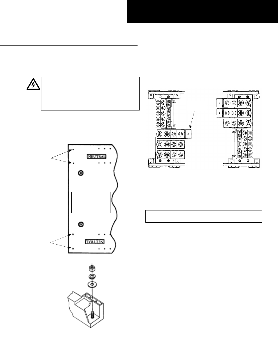
Neutral with Ground-Fault Sensor
5. To mount a neutral with ground-fault sensor, complete
steps 1–4. To test the installation, do the following:
• 800–1200 A: Loosen the
3
/
8
-16 nuts, as shown in
Figure 4, and remove the connector strap. After testing,
reassemble and tighten the nuts to 14 ft-lb.
• 400–600 A: loosen the
3
/
8
-16 nuts, as shown in Figure
5, and remove the sensor. After testing. reassemble and
tighten the nuts to 14 ft-lb.
GEH5585 Installation Instructions
R05
Install this box end
toward main
incoming line
(supply) cables
1
/
4
-20
Mounting
Studs
1
/
4
-20
Mounting
Studs
Bonding
Strap