GE Industrial Solutions A-Series II Panelboards SG User Manual
Page 3
DEH40150
DEH40150 Rev.No.03
3
[3] strap to C phase main busbar but adjacent to B phase branch base. All the
phase [1],[2], and [3] straps should be clamped with main bus using screws [7]
with 60 in-lb maximum torque.
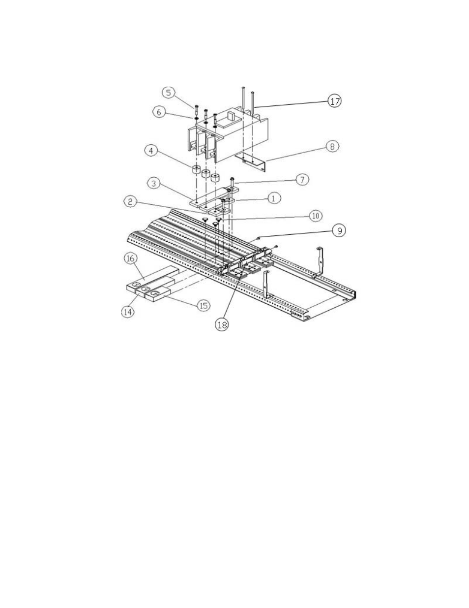
Figure 2. Installation of a SG circuit breaker kit on right side of interior, catalog number
ASPP6SG3S, into an A-Series
®
II panelboard.
8. Slide the insulator for A phase [15], B phase [14], C phase [16] cover over the
respective A, B, & C phase strap such that all the three insulators cut out made for
contact with the spool surface are in one line as shown in Fig.no.1 or Fig.no.2.
9. Mount bracket [8] on the interior rail with two screws [9] at the location defined
in Fig.no.1 and Fig.no.2 with 27-36 in-lb force.
10. Place the conical washer [6] over the three ¼-28 x 1
3
/
8
screws [5] and insert the
screws through the holes in the top of the circuit breaker terminals. Secure the
three spools [4] to the underside of the breaker terminals with the screws [5].
Take care to assemble the screws to the spools as shown in Fig.no.1 or Fig.no.2,
with the tapped end of the spool toward the breaker terminal.
11. Tighten the three ¼-28 X 1
3
/
8
screws [5] to 50-70 lb-in.
12. Place the breaker over the straps [1], [2], and [3] such that screws [5] align with
strap holes as shown in Fig.no.1 and Fig.no.2. Put two screw [17] with spring lock
washer #12 [19] in the breaker as shown in Fig.no.1 and Fig.no.2. Tighten these
screws to bracket [8] with 18-22 lb-in torque.
13. Remove the four screws [12] of existing filler plate from dead front where the
pro-stock SG breaker needs to be installed, as illustrated in Fig.no.3.