GE Industrial Solutions A-Series II Panelboards SG User Manual
Page 2
DEH40150
DEH40150 Rev.No.03
2
4. Locate the holes on the B and C phase main busbar over which C phase of breaker
mounting strap will crossover the main busbar after assembly of the breaker in
horizontal position as shown in the Fig.no.1 or Fig.no.2. Put xmas [10] tree over
the two aligned holes of B and C phase.
5. Similarly locate the holes of A phase main busbar over which B phase of breaker
mounting strap will crossover the main busbar after assembly of the breaker in
horizontal position as shown in the Fig.no.1 or Fig.no.2. Put xmas [10] tree over
the aligned hole of A phase.
6. Refer Fig.no.1 to mount the breaker on left side of interior. First mount the strap
for A phase [2] adjacent to crossbar [18] and insert the screw [7] through slot
provided for A phase to clamp it with main busbar. Similarly mount B phase [1]
strap to B phase main busbar but adjacent to A phase branch base, and C phase
[3] strap to C phase main busbar but adjacent to B phase branch base. All the
phase straps [1], [2], and [3] should be clamped with main bus using screws [7]
with 60 in-lb maximum torque.
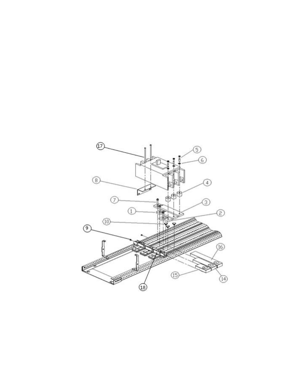
Figure 1. Installation of a SG circuit breaker kit on left side of interior, catalog number
ASPP6SG3S, into an A series
®
II panelboard.
7. Refer Fig.no.2 to mount the breaker on right side of interior. First mount the strap
for A phase [2] adjacent to cross bar [18] and insert the screw [7] through slot
provided for A phase to clamp it with main busbar. Similarly mount B phase [1]
strap to B phase main busbar but adjacent to A phase branch base, and C phase