Output, Through-hole, Soldering information – GE Industrial Solutions ESTW006A0B Series User Manual
Page 9
Data Sheet
November 5, 2012
ESTW006A0B Series Eighth-Brick Power Modules
36 - 75Vdc Input; 12V/6A
dc
Output
LINEAGE
POWER
9
Figure 14. T
ref
Temperature Measurement
Location for Module with Heat plate.
Heat Transfer via Convection
Increased airflow over the module enhances the heat
transfer via convection. Derating curves showing the
maximum output current that can be delivered by
each module versus local ambient temperature (T
A
)
for natural convection and up to 2m/s (400 ft./min)
forced airflow are shown in Figures 15 - 36.
Please refer to the Application Note ‘Thermal
Characterization Process For Open-Frame Board-
Mounted Power Modules’ for a detailed discussion of
thermal aspects including maximum device
temperatures.
O
U
TPU
T
CUR
RE
NT,
I
O
(A
)
AMBIENT TEMPERATURE, T
A
(
o
C
)
Figure 15. Output Current Derating for the Open
Frame Module; Airflow in the Transverse Direction
from V
out
(-) to V
out
(+); V
IN
=48.
O
U
TPU
T
CUR
RE
NT
, I
O
(A
)
AMBIENT TEMPERATURE, T
A
(
o
C
)
Figure 16. Output Current Derating for the Module
with Heat plate; Airflow in the Transverse
Direction from V
out
(-) to V
out
(+);V
IN
=48V.
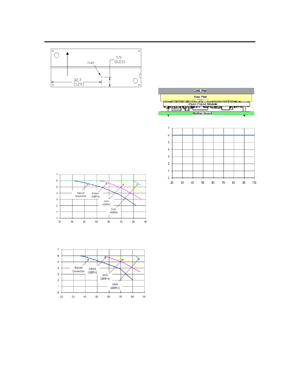
Heat Transfer via Conduction
The module can also be used in a sealed
environment with cooling via conduction from the
module’s top surface through a gap pad material to a
cold wall, as shown in Figure 19. This capability is
achieved by insuring the top side component skyline
profile achieves no more than 1mm height difference
between the tallest and the shortest power train part
that benefits from contact with the gap pad material.
The output current derating versus cold wall
temperature, when using a gap pad such as Bergquist
GP2500S20, is shown in Figure 20.
Figure 19. Cold Wall Mounting
O
U
TP
UT
CU
RRE
NT
, I
O
(A
)
COLD PLATE TEMPERATURE, T
C
(
o
C)
Figure 20. Derated Output Current versus Cold
Wall Temperature with Local Ambient
Temperature Around Module at 85C; V
IN
= 48V.
Through-Hole
Soldering Information
Lead-Free Soldering
The ESTW006A0Bxx RoHS-compliant through-hole
products use SAC (Sn/Ag/Cu) Pb-free solder and
RoHS-compliant components. They are designed to
be processed through single or dual wave soldering
machines. The pins have a RoHS-compliant finish
that is compatible with both Pb and Pb-free wave
soldering processes. A maximum preheat rate of
3
C/s is suggested. The wave preheat process
should be such that the temperature of the power
module board is kept below 210
C. For Pb solder,
the recommended pot temperature is 260
C, while the
Pb-free solder pot is 270
C max.
Paste-in-Hole Soldering
The ESTW006A0Bxx module is compatible with
reflow paste-in-hole soldering processes shown in
Figures 23-25. Since the ESTW006A0BxxZ module is
not packaged per J-STD-033 Rev.A, the module must
be baked prior to the paste-in-hole reflow process.
ESTW006A0Bxx-HZ modules are not compatible with
paste-in-hole reflow soldering. Please contact your
Lineage Power Sales Representative for further
information.
AIRFLOW