Output, Surface mount information, Continued) – GE Industrial Solutions ESTW006A0B Series User Manual
Page 11: Lead free soldering, Pb-free reflow profile, Post solder cleaning and drying considerations
Data Sheet
November 5, 2012
ESTW006A0B Series Eighth-Brick Power Modules
36 - 75Vdc Input; 12V/6A
dc
Output
LINEAGE
POWER
11
Surface Mount Information
(continued)
established by accurately measuring the modules CP
reliable soldering, the solder reflow profile should be
connector temperatures.
Lead Free Soldering
The –Z version of the ESTW006A0B modules are
lead-free (Pb-free) and RoHS compliant and are both
forward and backward compatible in a Pb-free and a
SnPb soldering process. Failure to observe the
instructions below may result in the failure of or cause
damage to the modules and can adversely affect
long-term reliability.
Pb-free Reflow Profile
Power systems will comply with J-STD-015 Rev. C
(Moisture/Reflow Sensitivity Classification for
Nonhermetic Solid State Surface Mount Devices) for
REF
L
O
W
T
E
MP
(
C)
REFLOW TIME (S)
Figure 23. Reflow Profile for Tin/Lead (Sn/Pb)
process.
M
AX TE
M
P
S
O
LD
ER
(
C)
Figure 24. Time Limit Curve Above 205
o
C for
Tin/Lead (Sn/Pb) process.
both Pb-free solder profiles and MSL classification
procedures. This standard provides a recommended
forced-air-convection reflow profile based on the
volume and thickness of the package (table 4-2). The
suggested Pb-free solder paste is Sn/Ag/Cu (SAC).
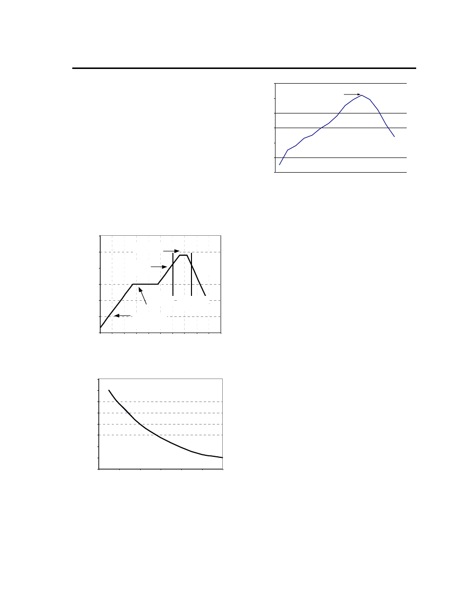
The recommended linear reflow profile using
Sn/Ag/Cu solder is shown in Figure 25.
Figure 25. Recommended linear reflow profile
using Sn/Ag/Cu solder.
Post Solder Cleaning and Drying
Considerations
Post solder cleaning is usually the final circuit board
assembly process prior to electrical board testing. The
result of inadequate cleaning and drying can affect
both the reliability of a power module and the
testability of the finished circuit board assembly. For
guidance on appropriate soldering, cleaning and
drying procedures, refer to Lineage Power Board
Mounted Power Modules: Soldering and Cleaning
Application Note (AN04-001).
0
50
100
150
200
250
300
Preheat zone
max 4
o
Cs
-1
Soak zo ne
30-240s
Heat zone
max 4
o
Cs
-1
Peak Temp 235
o
C
Coo ling
zone
1-4
o
Cs
-1
T
lim
above
205
o
C
200
205
210
215
220
225
230
235
240
0
10
20
30
40
50
60
Per J-STD-020 Rev. C
0
50
100
150
200
250
300
Reflow Time (Seconds)
Re
fl
o
w
T
em
p
(
°C
)
Heating Zone
1°C/Second
Peak Temp 260°C
* Min. Time Above 235°C
15 Seconds
*Time Above 217°C
60 Seconds
Cooling
Zone