Characteristic curves, Austin minilynx, Continued) – GE Industrial Solutions Austin Minilynx SMT User Manual
Page 8
Data Sheet
September 10, 2013
Austin MiniLynx
TM
SMT Non-isolated Power Modules:
2.4 – 5.5Vdc input; 0.75Vdc to 3.63Vdc Output; 3A output current
LINEAGE
POWER
8
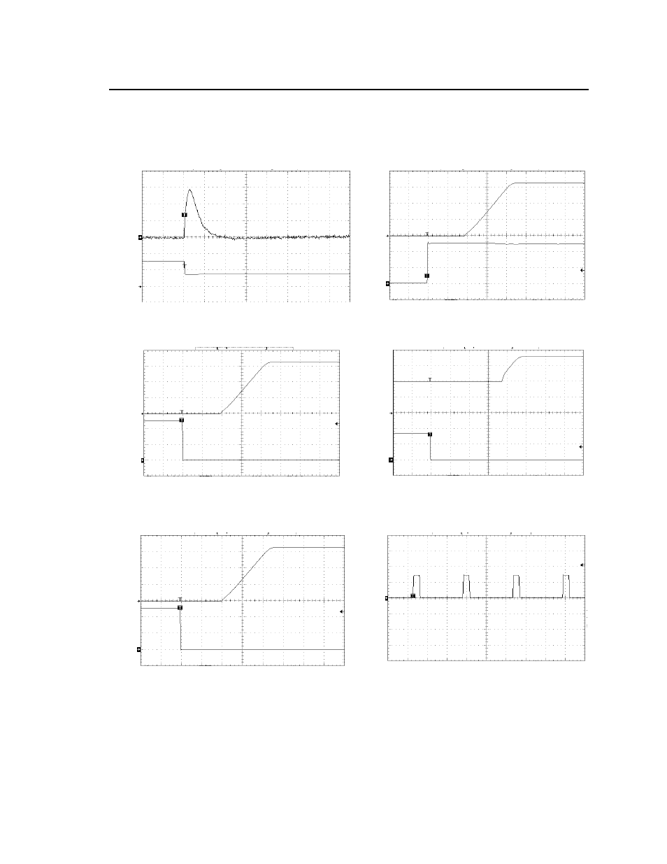
Characteristic Curves
(continued)
The following figures provide typical characteristics for the Austin MiniLynx
TM
SMT modules at 25ºC.
O
U
T
P
UT
CU
RR
E
N
T
,
O
U
T
P
UT
V
O
LT
A
G
E
I
O
(A
) (2
A
/d
iv)
V
O
(
V
) (20mV/
di
v)
IN
P
U
T
V
O
LT
A
G
O
U
T
P
UT
VO
LT
AG
E
V
IN
(V
) (
2V
/div)
V
O
(V
) (1
V
/d
iv)
TIME, t (100
μs/div)
TIME, t (2ms/div)
Figure 13. Transient Response to Dynamic Load
Change from 100% of 50% full load (Vo = 3.3Vdc, Cext
= 2x150 μF Polymer Capacitors).
Figure 16. Typical Start-Up with application of Vin
(V
IN
= 5.0Vdc, Vo = 3.3Vdc, Io = 3A).
ON
/O
F
F
V
O
LT
A
G
E
O
U
T
P
UT
V
O
LT
AG
E
V
On
/o
ff
(V
) (2
V
/d
iv
)
V
O
(
V
)
(1
V
/d
iv
)
ON
/O
F
F
V
O
LT
A
G
E
O
U
T
P
UT
V
O
LT
AG
E
V
O
n/o
ff
(V
) (
2
V
/d
iv
)
V
O
(
V
)
(0
.5
V
/di
v)
TIME, t (2ms/div)
TIME, t (2ms/div)
Figure 14. Typical Start-Up Using Remote On/Off
(V
IN
= 5.0Vdc, Vo = 3.3Vdc, Io = 3A).
Figure 17 Typical Start-Up Using Remote On/Off
with Prebias (V
IN
= 3.3Vdc, Vo = 1.8Vdc, Io = 1.0A,
Vbias =1.0Vdc).
O
N
/O
FF VO
LTAG
E
OU
T
P
U
T
V
O
LT
AG
E
V
On
/o
ff
(V
) (2
V
/di
v)
V
O
(
V
)
(1
V
/di
v)
O
U
T
P
UT
C
U
R
R
E
N
T
,
I
O
(
A
) (5
A
/d
iv
)
TIME, t (2ms/div)
TIME, t (10ms/div)
F
igure 15. Typical Start-Up Using Remote On/Off with
Low-ESR external capacitors (7x150uF Polymer)
(
V
IN
= 5.0Vdc, Vo = 3.3Vdc, Io = 3A, Co = 1050
μF).
Figure 18. Output short circuit Current
(V
IN
= 5.0Vdc, Vo = 0.75Vdc).