GE Industrial Solutions SDCJBBC User Manual
Page 6
GEH-704 Installation Instructions
Connections
The Advanced Distribution Cable Junction Box has five
additional connectors, which are labeled by function
for clarity. The four-pin receptacle is used for the
connection of a neutral current sensor signal (2 pins)
and an auxiliary switch signal (2 pins) into the breaker.
The three-pin terminal block is for the communication
wiring. The black four-pin terminal is used for the input
and output connections for zone selective interlock
(ZSI), the two-pin connector is used for the input of
reduced energy let-through (RELT) wiring, and the last
four-pin receptacle is used for ground fault alarm (GFA)
and RELT output connections.
Note: If the Spectra
®
RMS Molded-Case Circuit Breaker
with a microEntelliGuard
TM
Trip Unit has the ground
fault option AND is connected to either a three phase/
four wire system or single phase/three wire system,
then a neutral input is required for the circuit breaker to
function properly. A Neutral CT is also required for Trip
Units optioned with neutral protection.
The connectors are a .200" on-center European
Style receptacle such that stripped wire (AWG #12-
26) can be used. The recommended torque for the
connector screws is 5 in-Ibs. This connector is keyed
to help prevent incorrect mating. When connecting
to the four-pin connectors, it is recommended that
two 2-pin connectors be used, one for auxiliary
switch connections, one for neutral current sensor
connections, etc… (although one 4-pin may be used).
Neutral
A Neutral CT is required for advanced features such
as ground fault, ground fault alarm, and neutral
protection. The neutral input is accomplished by
connecting a neutral current sensor between the
system neutral (line) and breaker neutral (load), then
wiring the BLACK and WHITE neutral current sensor
screw terminals to the two screw terminals of the
plug connector. This junction box connector is then
plugged into the front face of the 4-pin receptacle of
the Advanced Distribution Cable Junction Box labeled
“CT COM” (white wire) and “CT N” (black wire). Available
neutral transformers are shown in the following table.
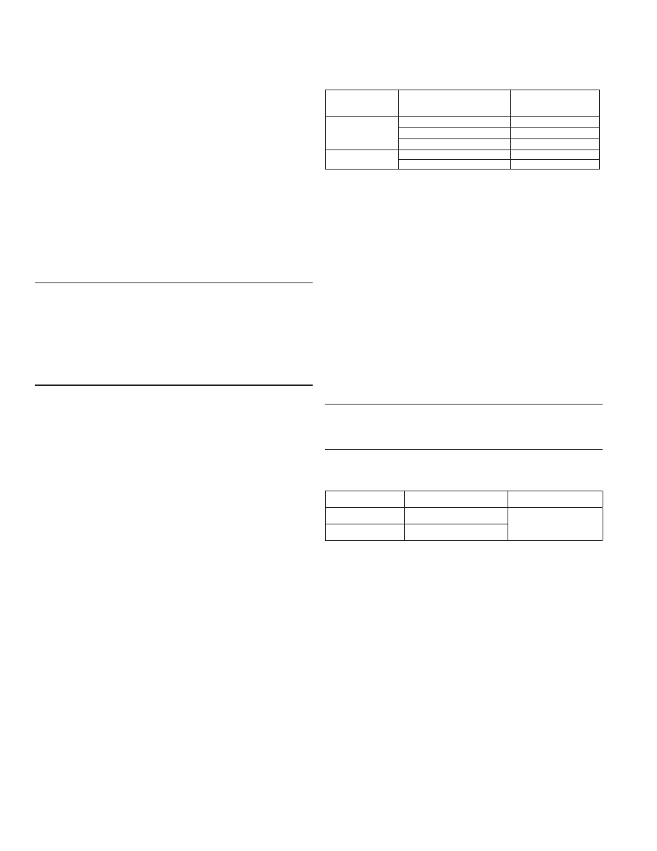
Table 1. Neutral Transformers
Breaker Type
Breaker Current Sensor
Rating (S)
Catalog Number
150
TSRG201
SG
400
TSRG204
600
TSRG206
SK
800
TSKG408
1200
TSKG412
Auxiliary Switch
Spectra
®
RMS Molded-Case Circuit Breakers with
microEntelliGuard
TM
Trip Units require an auxiliary
switch mounted in the right side accessory pouch to
provide a breaker position signal via communication
network. The switch is a form C contact and is used to
convey breaker position (closed or open). This position
input signal is accomplished by connecting the red and
white auxiliary switch leads to the two screw terminals
of the plug connector. This connector is then plugged
into the front face of the 4-pin receptacle of the
Advanced Distribution Cable Junction Box labeled “AUX
SW-” (white) and “AUX SW+” (red).
Note: The microEntelliGuard™ Trip Unit requires an
Auxiliary Switch with gold plated contacts
(Use table below).
Table 2. Auxiliary Switches
Catalog Number No. of Switch Elements Switch Rating
SAUXGAB1
1 form C
Gold-Plated Contacts
0.5 A @ 30 V
SAUXGAB2
2 form C
Modbus Communications
Spectra
®
RMS
Breakers with microEntelliGuard
TM
Trip Units communicate via a modbus link, which is
accomplished by connecting the clear, black, and shield
leads of AWG #16 twisted shielded wire (Belden 9841) to
the three screw terminals on the Advanced Distribution
Cable Junction Box labeled Modbus RX, Modbus TX, and
Modbus Shld. Communication links between similar
breakers may be daisy chained between Advanced
Distribution Cable Junction Boxes (refer to Figure 5).
The wiring should begin at the master device and wire
from device to device. At the end of the wiring chain
the last connection should be to the Multilin Modbus
terminator (RC network part number is 1810-0106).
The Tx connection should connect to other Mod-bus Tx
(+) connections. The Rx connection should connect to
other Modbus Rx (-) connections.