GE Industrial Solutions SDCJBBC User Manual
Page 3
GEH-704 Installation Instructions
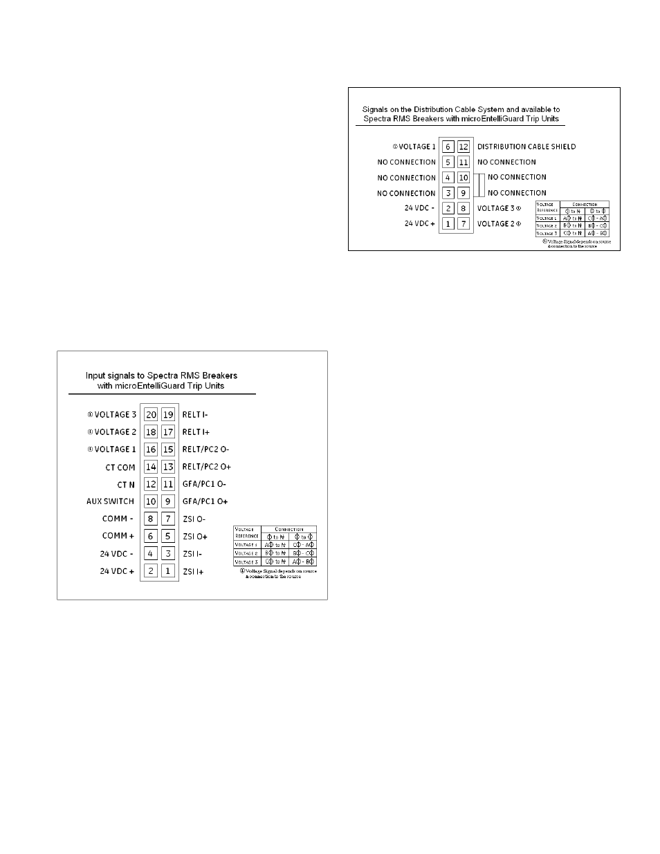
The Advanced Distribution Cable Junction Box has a 20-
pin plug connector on the front face labeled “BREAKER”.
This connector mates to the 20-pin receptacle
connector of the Spectra
®
RMS Molded-Case Circuit
Breaker with a microEntelliGuard
TM
Trip Unit. Figure 2
shows this “BREAKER” input connector pinout for the
Advanced Distribution Cable Junction Box.
The Advanced Distribution Cable Junction Box also
has two 12-pin plug connectors on the front face
labeled “HARNESS”. These connectors mate with the
12-pin receptacle connectors of a Distribution Cable
Harness (cat. nos. SDCHA11, SDCHA30 or SDCHA60). By
connecting to these plugs, the Advanced Distribution
Cable Junction Box provides a connection into or
out of the Distribution Cable System. Figure 3 shows
the “HARNESS” connector pinout for the Advanced
Distribution Cable Junction Box.
Figure 2. BREAKER input pinout connections for the Advanced
Distribution Cable Junction Box.
Figure 3. HARNESS pinout connections for the Advanced
Distribution Cable Junction Box.
The system is used to carry a variety of electronic signals
between Spectra
®
RMS Molded-Case Circuit Breakers
with microEntelliGuard
TM
Trip Units and Distribution
Cable accessories. The electronic signals supported by
the Distribution Cable System are as follows.
Spectra
®
RMS Breaker with microEntelliGuard
TM
Trip Unit
• control power (+24vdc;)
• control power (common)
• voltage A f (must be from Voltage Module or Voltage
Conditioner Plate or Voltage Conditioner Assembly)
• voltage B f (must be from Voltage Module or Voltage
Conditioner Plate or Voltage Conditioner Assembly)
• voltage C f (must be from Voltage Module or Voltage
Conditioner Plate or Voltage Conditioner Assembly)