Geh-5889p2 – GE Industrial Solutions Spectra Series Fusible Switch Units H, K & R User Manual
Page 2
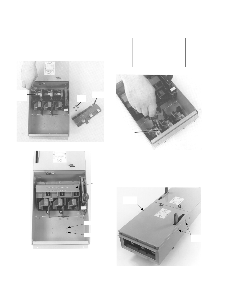
4. Install the kit. Remove and save the hex nuts from
the studs and the red arc cover on the expansion
switch, as shown in Figure 4. Install the expansion
plate into the enclosure, positioning the switch base
over the connecting straps. Install 10-32 screws with
washers into the connecting straps inside the switch
base. Tighten the screws to 27–32 in-lb.
Replace the hex nuts back onto the plate studs and
tighten to 27–32 in-lb. Replace the red arc cover, as
shown in Figure 5, and tighten the screws to 12–15
in-lb.
Figure 4. Installing the expansion plate into the enclosure.
Figure 5. Replacing the arc cover.
5. Install the load base. Install the load base into the
enclosure, as shown in Figure 6. The position
depends on the fuse type, as illustrated in Figure 5
and listed in Table 1. Tighten the mounting screws
to 40–50 in-lb.
Position Fuse
Type
1
H Fuse 240 V
K Fuse 240 V
R Fuse 240 V
2
H Fuse 600 V
K Fuse 600 V
R Fuse 600 V
Table 1. Position for the load base in the enclosure.
Figure 6. Installing the load base.
6. Install the cover. Install 10-32 x
1
/
4
" screws into the
mechanism shroud mounting holes, as shown in
Figure 7. Position the new enclosure cover in place
on the enclosure and secure with 10-32 x
1
/
4
" screws.
Tighten all screws to 27–32 in-lb. Reinstall the switch
into the panelboard and secure the rail latch locking
screws.
Figure 7. Installing the cover on the enclosure.
#10-32
Screw with
Washer
Hex
Nuts
Red Arc
Cover
Position 1
Position 2
Arc
Cover
Load
Base
Enclosure
Cover
Mounting
Holes