GE Industrial Solutions Spectra Series Power Panelboards AMCB2GM and AMCB3GM User Manual
Page 7
7
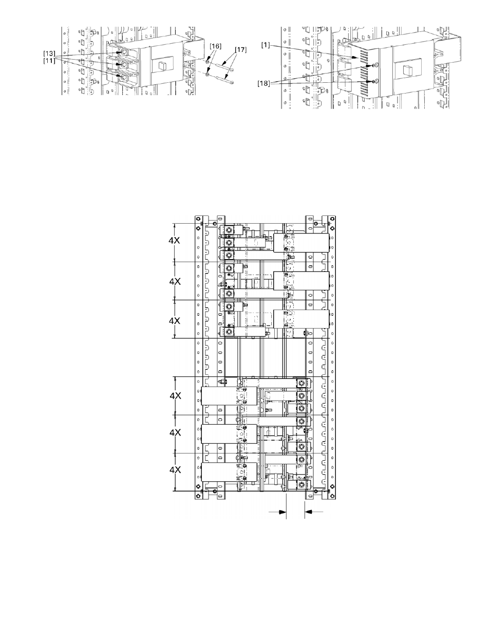
Figure 33. Installing a circuit breaker.
8. Tigthen the bolted connections.
Tighten the bolted
strap connections to the vertical bus to 65 in-lb. It may
be necessary to remove an adjacent breaker to allow
access to the bolted connections at the vertical bus.
9. Terminal cover installation.
Install the terminal cover
[1] to the breaker with thread-cutting screws [18], as
shown in Figure 34. A
3
/
8
" x
3
/
8
" relief hole must be
made in the cover if the breaker is mounted as a main
with an accessory cable (such as ground fault and
communications) leaving the load end of the breaker.
Figure 34. Installing the terminal cover on the breaker.
10. Breaker mounting configurations.
For phase-
balancing, single-phase panels, and dc applications,
refer to Figure 35 for the breaker mounting
configurations available with these strap kits. When
installing these strap configurations, be sure to use
standard phase rotation, as required.
Figure 35. Possible bus strap combinations. Note that if the 2.75" reference dimension is on the left side of the panel,
this diagram should be flipped 180° for the appropriate view.
Cable connection on
2.75" reference side.
Cable connection
opposite to 2.75"
reference side.
3-pole main or
branch breaker,
A, B, & C
ø
location.
2-pole main or
branch breaker,
A & C
ø
location.
2-pole main or
branch breaker,
A & B
ø
location.
3-pole main or
branch breaker,
A, B, & C
ø
location.
2-pole main or
branch breaker,
A & C
ø
location.
2-pole main or
branch breaker,
A & B
ø
location.
2.75" REF