Deh-060p5-p8 – GE Industrial Solutions Spectra Series Power Panelboards AMCB2GM and AMCB3GM User Manual
Page 5
5
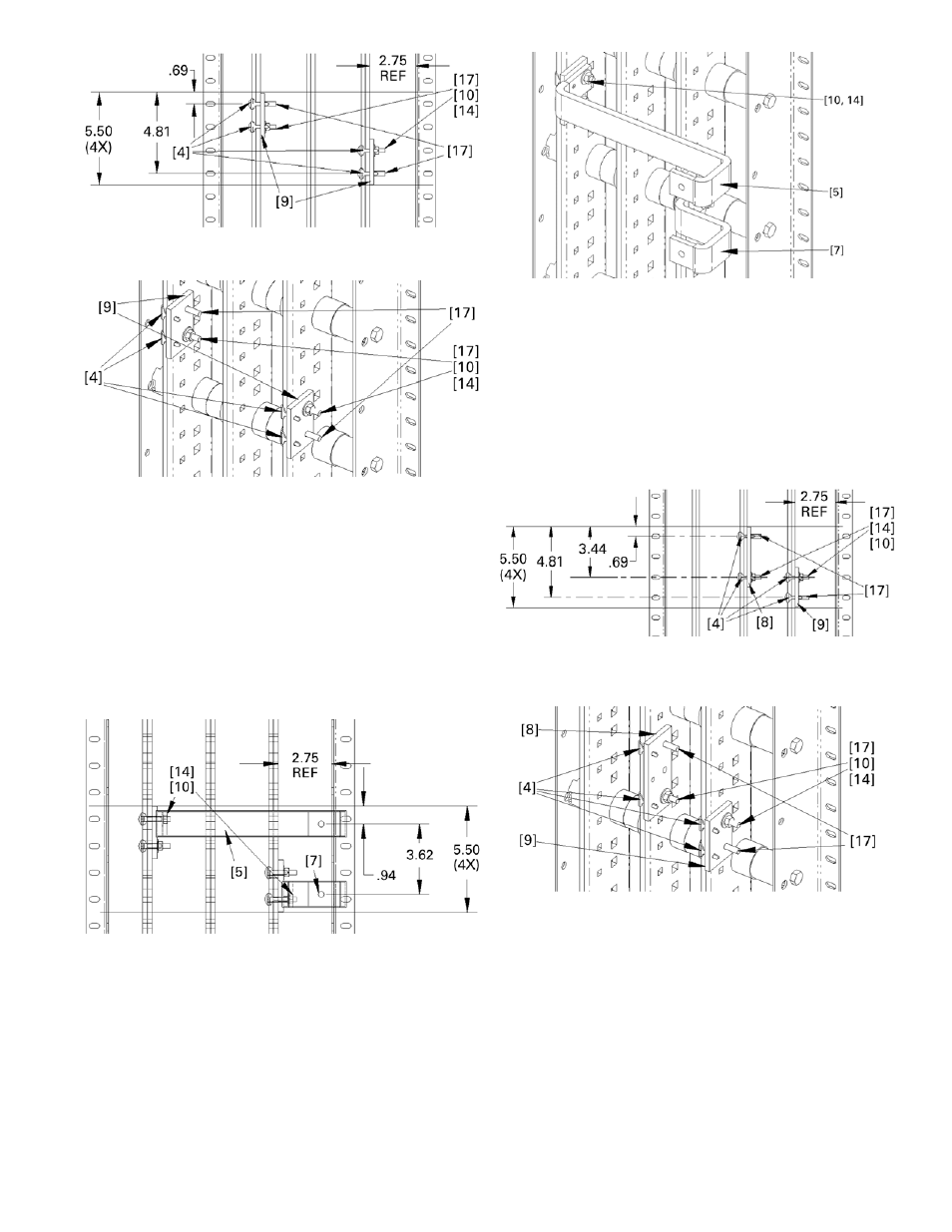
Figure 21. Carriage bolt, antiturn clip, and spacer installation for
connections to the outer bus of three-phase interiors.
Figure 22. Carriage bolt, antiturn clip, and spacer installation for
connections to the outer bus of three-phase interiors, isometric view.
5d. Install straps.
Place the G frame single straps [5,
7] over the carriage bolts and antiturn clips, as
shown in Figures 23 and 24. Place conical washers
[10] on the bolts and secure with nuts [14]. Leave
the connections finger tight.
If the group assembly selection is for connections
to the outer vertical bus with the cable
connections on the opposite side from the 2.75"
reference dimension, and the assembly looks like
Figure 24, then go to step 6.
Figure 23. Installing the straps for connections to the outer bus of
three-phase interiors.
Figure 24. Installing the straps for connections to the outer bus of
three-phase interiors, isometric view.
5e. Strap connections to the middle vertical bus and
the vertical bus on the same side as the 2.75"
reference dimension.
Position the carriage bolts [17], antiturn clips [4],
and spacers [8, 9] as shown in Figures 25 and 26.
Place conical washers [10] on the bolts shown and
secure with nuts [14]. Leave the connections
finger tight.
Figure 25. Carriage bolt, antiturn clip, and spacer installation for
single-phase applications with connections to the middle vertical
bus.
Figure 26. Carriage bolt, antiturn clip, and spacer installation for
single-phase applications with connections to the middle vertical
bus, isometric view.
5f. Install straps.
Place the G frame single straps [6,
7] over the carriage bolts and antiturn clips, as
shown in Figures 27 and 28. Place conical washers
[10] on the bolts and secure with nuts [14]. Leave
the connections finger tight.
If the group assembly selection is for connections
to the outer vertical bus with the cable
connections opposite to the 2.75" reference
dimension, and the assembly looks like Figure 28,
then go to step 6.
Edge of G
Frame
Edge of G
Frame
Edge of G Frame
Edge of G Frame
Edge of G Frame
Edge of G Frame