Surface mount information, Austin microlynx, Pick and place – GE Industrial Solutions Austin Microlynx II SMT User Manual
Page 19: Nozzle recommendations, Tin lead soldering
Data Sheet
September 10, 2013
Austin MicroLynx
TM
II SMT Non-isolated Power Modules:
2.4 – 5.5Vdc input; 0.75Vdc to 3.63Vdc Output; 6A output current
LINEAGE
POWER
19
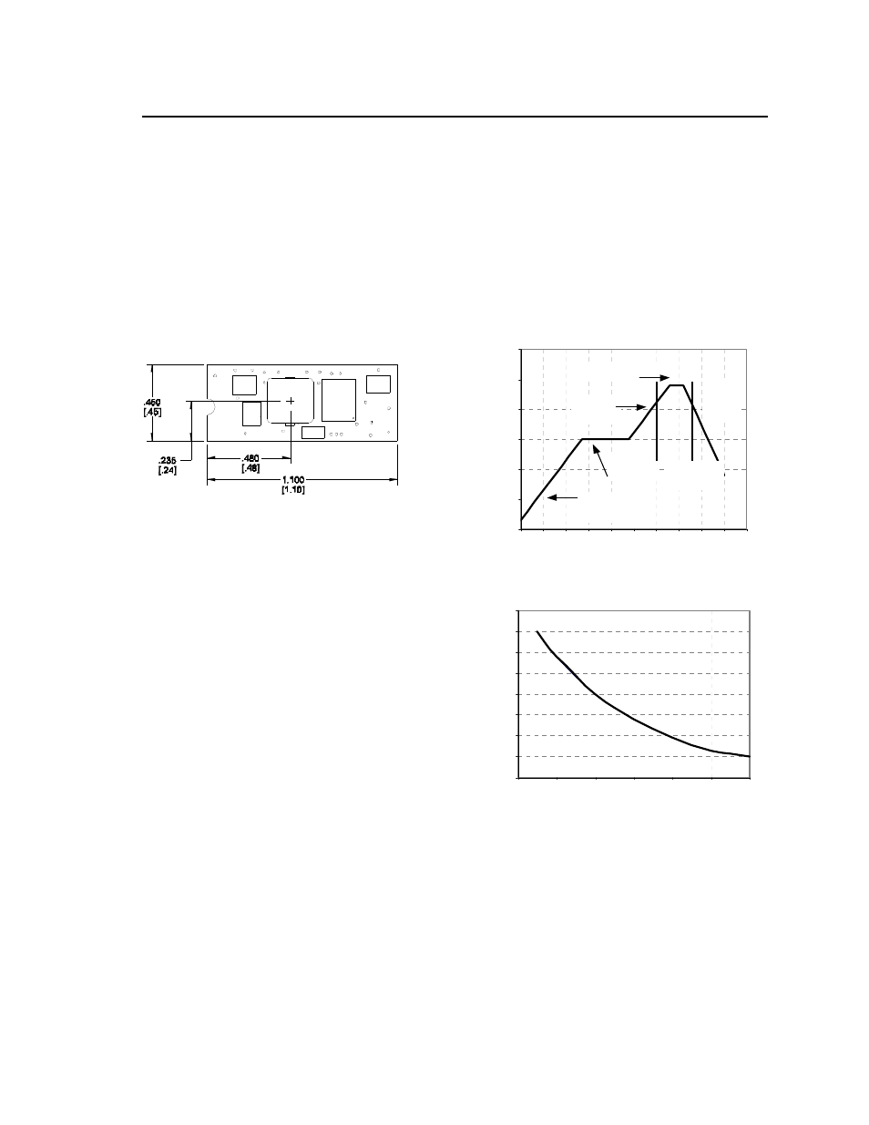
Surface Mount Information
Pick and Place
The Austin MicroLynx
TM
II SMT modules use an open
frame construction and are designed for a fully
automated assembly process. The modules are fitted
with a label designed to provide a large surface area
for pick and placing. The label meets all the
requirements for surface mount processing, as well as
safety standards and is able to withstand maximum
reflow temperature. The label also carries product
information such as product code, serial number and
location of manufacture.
Figure 34. Pick and Place Location.
Nozzle Recommendations
The module weight has been kept to a minimum by
using open frame construction. Even so, these
modules have a relatively large mass when compared
to conventional SMT components. Variables such as
nozzle size, tip style, vacuum pressure and pick &
placement speed should be considered to optimize
this process. The minimum recommended nozzle
diameter for reliable operation is 3mm. The maximum
nozzle outer diameter, which will safely fit within the
allowable component spacing, is 8 mm max.
Tin Lead Soldering
The Austin MicroLynx
TM
II SMT power modules are
lead free modules and can be soldered either in a
lead-free solder process or in a conventional Tin/Lead
(Sn/Pb) process. It is recommended that the
customer review data sheets in order to customize the
solder reflow profile for each application board
assembly. The following instructions must be
observed when soldering these units. Failure to
observe these instructions may result in the failure of
or cause damage to the modules, and can adversely
affect long-term reliability.
In a conventional Tin/Lead (Sn/Pb) solder process
peak reflow temperatures are limited to less than
235
o
C. Typically, the eutectic solder melts at 183
o
C,
wets the land, and subsequently wicks the device
connection. Sufficient time must be allowed to fuse
the plating on the connection to ensure a reliable
solder joint. There are several types of SMT reflow
technologies currently used in the industry. These
surface mount power modules can be reliably
soldered using natural forced convection, IR (radiant
infrared), or a combination of convection/IR. For
reliable soldering the solder reflow profile should be
established by accurately measuring the modules CP
connector temperatures.
R
E
FLOW
TEM
P
(°
C)
0
50
100
150
200
250
300
Preheat zo ne
max 4
o
Cs
-1
Soak zo ne
30-240s
Heat zone
max 4
o
Cs
-1
Peak Temp 235
o
C
Co oling
zone
1-4
o
Cs
-1
T
lim
above
205
o
C
REFLOW TIME (S)
Figure 35. Reflow Profile for Tin/Lead (Sn/Pb)
process.
MAX
TE
MP
S
O
LD
E
R
(°
C)
200
205
210
215
220
225
230
235
240
0
10
20
30
40
50
60
Figure 36. Time Limit Curve Above 205
o
C for
Tin/Lead (Sn/Pb) process.