Data sheet, Electrical specifications (continued), Isolation specifications – GE Industrial Solutions EBDW020A0B Barracuda Series User Manual
Page 3
GE
Data Sheet
EBDW020A0B Barracuda™ Series; DC-DC Converter Power Modules
36-75Vdc Input; 12.0Vdc, 20.0A, 240W Output
April 15, 2013
©2012 General Electric Company. All rights reserved.
Page 3
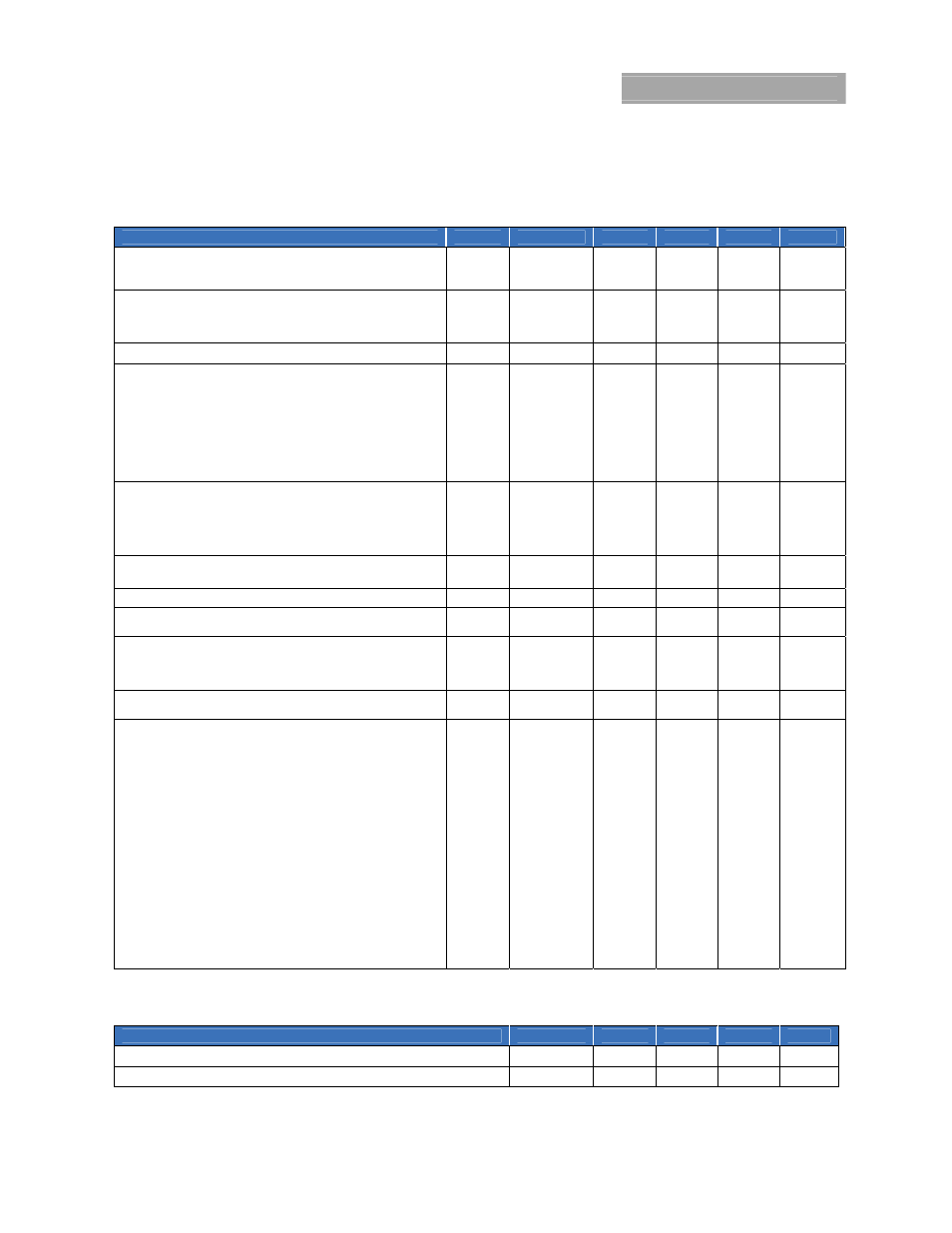
Electrical Specifications (continued)
Unless otherwise indicated, specifications apply over all operating input voltage, resistive load, and temperature conditions.
Parameter
Device
Symbol
Min
Typ
Max
Unit
Output Voltage Set-point (Default)
(V
IN
=V
IN,nom
, I
O
=10A, T
A
=25°C)
(Adjustable via PMBus)
All V
O, set
11.97 12.00 12.03 V
dc
Output Voltage Variation from Default
(Over all operating input voltage (40V to 75V), resistive load, and
temperature conditions until end of life)
All w/o -P
V
O
11.76
12.24
V
dc
-P Option
V
O
11.63
12.37 V
dc
Output Voltage (V
IN
=36V, T
A
= 25ºC)
All
V
O
10.8
V
dc
Output Regulation [V
IN, min
= 40V]
Line (V
IN
=V
IN, min
to V
IN, max
)
All w/o -P
0.2
% V
O, set
Load (I
O
=I
O, min
to I
O, max
)
All w/o -P
0.2
% V
O, set
Line (V
IN
=V
IN, min
to V
IN, max
) -P
Option
0.5
% V
O, set
Load (I
O
=I
O, min
to I
O, max
), Intentional Droop
-P Option
0.50
V
dc
Temperature (T
A
= -40ºC to +85ºC)
All
2
% V
O, set
Output Ripple and Noise on nominal output
(V
IN
=V
IN, nom
and I
O
=I
O, min
to I
O, max
)
RMS (5Hz to 20MHz bandwidth)
All
70
mV
rms
Peak-to-Peak (5Hz to 20MHz bandwidth)
All
200
mV
pk-pk
External Output Capacitance
All w/o -02
All w -02
C
OUT
C
OUT
220
220
1
10,000
10,000
μF
μF
Output Current
All
I
O
0 20
A
dc
VOUT_OC_FAULT_LIMIT (Default)
(Adjustable via PMBus)
All w/o -02
All w -02
I
O,lim
I
O,lim
23
28
A
dc
A
dc
Efficiency (V
IN
=V
IN, nom
, V
O
= V
O,set
,
T
A
=25°C)
I
O
= 100% I
O, max
All
η
95.2 %
I
O
= 55% - 90% I
O, max
All
η
95.4 %
Switching Frequency (primary MOSFETs)
(Output Ripple 2X switching frequency)
f
sw
150 kHz
Dynamic Load Response
(dI
O
/d
t
=1A/10s; V
in
=V
in
,
nom
; T
A
=25°C; tested with a 10μF
ceramic and 1 x 470μF polymer capacitor across the load.)
Load Change from I
O
= 50% to 75% of I
O,max
:
Peak Deviation
Settling Time (V
O
<10% peak deviation)
All w/o -
02
V
pk
t
s
__
__
750
800
__
__
mV
pk
s
Load Change from I
O
= 75% to 50% of I
O,max
:
Peak Deviation
Settling Time (V
O
<10% peak deviation)
All w/o -
02
V
pk
t
s
__
__
750
800
__
__
mV
pk
s
(dI
O
/d
t
=1A/10s; V
in
=V
in
,
nom
; T
A
=25°C; tested with a 10μF
ceramic and 1 x 220μF polymer capacitor across the load.)
Load Change from I
O
= 50% to 75% of I
O,max
:
Peak Deviation
Settling Time (V
O
<10% peak deviation)
All w -02
V
pk
t
s
__
__
300
700
__
__
mV
pk
s
Load Change from I
O
= 75% to 50% of I
O,max
:
Peak Deviation
Settling Time (V
O
<10% peak deviation)
All w -02
V
pk
t
s
__
__
300
700
__
__
mV
pk
s
Note (1): Polymer capacitors required.
Isolation Specifications
Parameter
Symbol
Min
Typ
Max
Unit
Isolation Capacitance
C
iso
1000
pF
Isolation Resistance
R
iso
10
MΩ