Installing the phase sensors (cts), Assembling, Ct to the bus – GE Industrial Solutions ProTrip Conversion Kits DB-25, DBL-25, DB-50, DBL-50 User Manual
Page 9: Ct assembly for a db-50 breaker
3. On DB-25 breakers only, insert the bus alignment
dowel into the hole below each load terminal, as
shown in Figure 10.
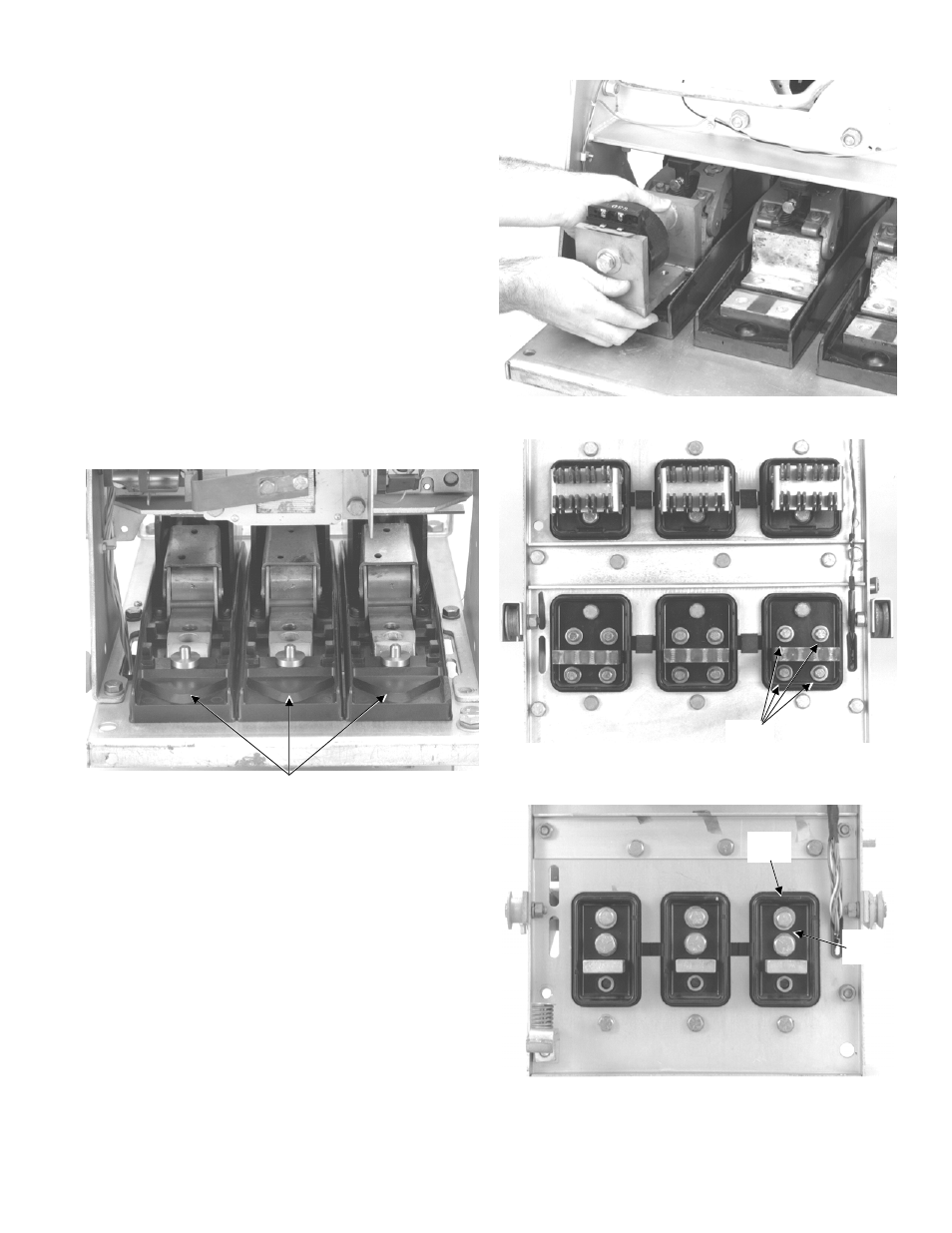
4. Place each CT assembly into the breaker, as shown
in Figure 11, carefully aligning the tapped holes in
the bus with the existing holes in the back frame.
5. On a DB-50 breaker, insert the four
3
/
8
-16 x 2
1
/
2
"
bolts, with lock washers and flat washers, through
the back of the breaker into the tapped holes in the
CT assemblies, as shown in Figure 12. Leave the
bolts finger tight for now.
On a DB-25 breaker, insert a single
1
/
2
-13 x 2
1
/
4
"
bolt, with a lock washer and flat washer, through the
hole immediately above the load terminal on the back
of the breaker into the tapped hole in the CT
assembly, as shown in Figure 13. Insert the
3
/
8
-16 x
2" bolt, with a lock washer and flat washer, through
the second hole above the load terminal.
A breaker with all three CT assemblies installed in
shown in Figure 14.
Figure 10. CT alignment dowels installed on a DB-25
breaker.
Figure 11. Placing a CT into position on a DB-50 breaker.
Figure 12. CT bolts inserted into a DB-50 breaker back
frame.
Figure 13. CT bolts inserted into a DB-25 breaker back
frame.
CT Alignment
Dowel
3
/
8
Bolts
-16
3
/
8
-16
Bolt
1
/
2
-13
Bolt
9