Removing the electromechanical trip devices – GE Industrial Solutions ProTrip Conversion Kits DB-25, DBL-25, DB-50, DBL-50 User Manual
Page 5
SECTION 3. BACK FRAME BREAKER
CONVERSION
The back frame conversion of a Westinghouse
®
DB-25,
DBL-25, DB-50, or DBL-50 breaker consists of the
following steps:
1. Remove the breaker to a clean, well-lighted work
bench and place it upright, so that both the front and
back are easily accessible, as shown in Figure 1.
2. Remove the existing electromechanical trip devices.
3. Assemble the phase sensors (CTs) to their bus
structures.
4. Install the CT assemblies on the breaker.
Removing the Electromechanical Trip
Devices
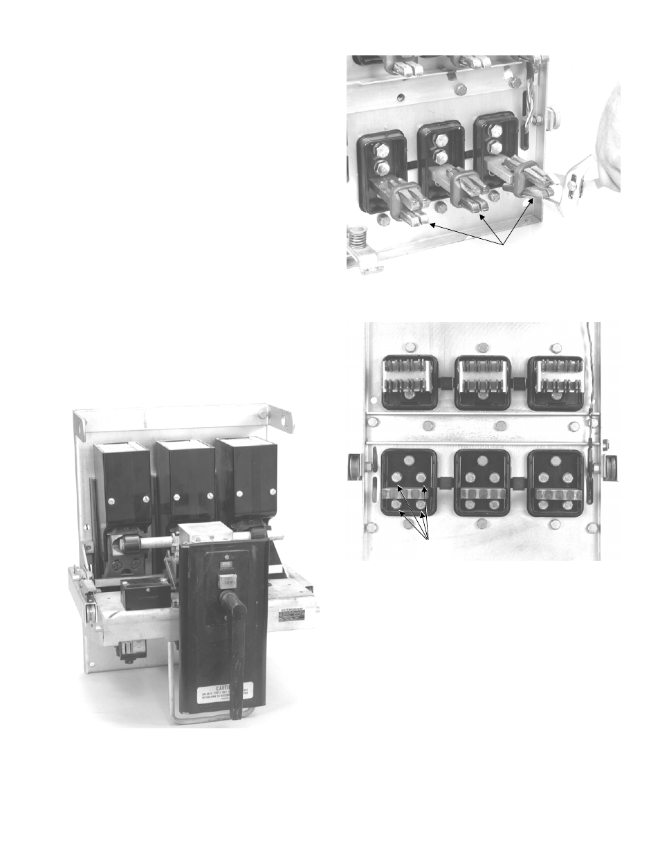
1. On a draw-out breaker, remove the load-side draw-
out contact fingers. Use a pair of pliers to squeeze
the fingers and release them from the load terminals,
as shown in Figure 2.
2. On both a DB-25 and DB-50 breaker, remove and
discard the two
1
/
2
-13 bolts above each load
terminal, as shown in Figures 3 and 4.
Figure 1. Westinghouse DB-50 breaker removed from its
enclosure and ready for conversion.
Figure 2. Removal of the load-side draw-out fingers from
a DB-25 breaker.
Figure 3. Trip unit mounting bolts to be removed from a
DB-50.
Load-Side
Draw-Out
Fingers
1
/
2
-13
Bolts
5