Thermal considerations, Air flow t – GE Industrial Solutions Austin Minilynx 12V SMT User Manual
Page 14
Data Sheet
September 10, 2013
Austin MiniLynx
TM
12V SMT Non-isolated Power Modules:
8.3 – 14Vdc input; 0.75Vdc to 5.5Vdc Output; 3A output current
LINEAGE
POWER
14
Thermal Considerations
Power modules operate in a variety of thermal
environments; however, sufficient cooling should be
provided to help ensure reliable operation.
Considerations include ambient temperature, airflow,
module power dissipation, and the need for increased
reliability. A reduction in the operating temperature of
the module will result in an increase in reliability. The
thermal data presented here is based on physical
measurements taken in a wind tunnel. The test set-
up is shown in Figure 32. Note that the airflow is
parallel to the long axis of the module as shown in
figure 31. The derating data applies to airflow in
either direction of the module’s long axis.
Air Flow
T
ref
Figure 31. Tref Temperature measurement
location.
The thermal reference point, T
ref
used in the
specifications is shown in Figure 32. For reliable
operation this temperature should not exceed 115
o
C.
The output power of the module should not exceed
the rated power of the module (Vo,set x Io,max).
Please refer to the Application Note “Thermal
Characterization Process For Open-Frame Board-
Mounted Power Modules” for a detailed discussion of
thermal aspects including maximum device
temperatures.
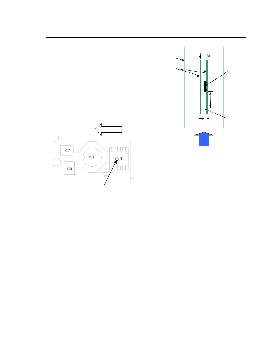
Figure 32. Thermal Test Set-up.
Heat Transfer via Convection
Increased airflow over the module enhances the heat
transfer via convection. Thermal derating curves
showing the maximum output current that can be
delivered by various module versus local ambient
temperature (T
A
) for natural convection and up to
0.5m/s (100 ft./min) are shown in the Characteristics
Curves section.
Air
flow
x
Power Module
Wind Tunnel
PWBs
5.97_
(0.235)
76.2_
(3.0)
Probe Location
for measuring
airflow and
ambient
temperature
25.4_
(1.0)