Step 2- installation – GE Industrial Solutions Record Plus Plug-In Bases: FC100 User Manual
Page 3
Step 2- Installation
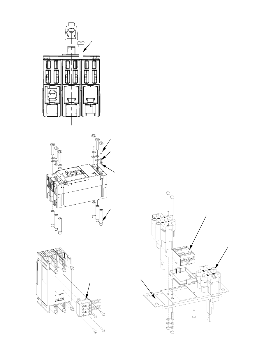
1. Remove the lugs from breaker (if installed), as
illustrated in Figure 4.
2. Replace each lug with male plug (4) and fasten them
to breaker terminal with # 10-32 X 0.625” screw [1]
and lock washer [2] and flat washer [3], as illustrated
in Figure 5. Tighten the screws to 27 - 32 in-lb.
[14]
3. Fasten the Secondary Disconnect breaker adaptor
(FCDSDB) [10] to the breaker base with #4-40 X
0.312” screw provided in kit, as illustrated in Figure 6.
Tighten the screws to 5 - 6 in-lb.
4. Mount plug-in base (6) with #10-24x1.75” screw [5],
nut [7], lock washer [2] and washer [3] to proper
support*, using the dimension shown in the table
and drawing for location of boltholes, as illustrated in
Figures 8 & 9. Tighten the screws to 23 - 28 in-lb.
5.
Fasten the Secondary Disconnect Base (FCDSDP) [9]
to proper support or Mounting plate [8] with thread
cutting screw #8-32X0.375” provided in kit, as
illustrated in Figure 7. Tighten the screws 16 to 20 in-
lb.
Figure 4. Remove the lugs from breaker.
Figure 5. Assemble Male Plugs to Breaker terminals.
[4]
[1]
[3]
[2]
NOTE: Use # 8-32 X 2.875” long screws to mount FC100
circuit breaker. If mounting screws other than those
provided are used, threads must be class 2 and free of
burs and deformation.
*Optional Mounting plate [8], available and used for
dead front panel construction, can also be used as
“templates” in mounting plugin bases.
[9] FCDSDP
Figure 7.Assemble Plugin Base and Secondary
Disconnect Bottom Holder on Mounting plate.
[6] FCDDF1
FCDDF2
FCDDF3
FCDDF4
Figure 6.Assemble the Secondary Disconnect
Breaker Adaptor to Breaker.
[10] FCDSDB
[8]