GE Industrial Solutions Power Mark Gold Load Centers User Manual
Indoor type, Powermark gold ™load centers
DEH - 40537 Installation Instructions
For
100-225 Ampere Single Phase 12-42 Circuit
g
PowerMark Gold ™Load Centers
Indoor Type
General
To comply with the National Electrical Code and
Underwriters Laboratories, the load center must be
installed in accordance with the information included on
the label on the inside of the equipment. This must also
be done in accordance with applicable local electrical
codes, and by a qualified electrical contractor and/or
licensed electrician.
WARNING: Hazard of electrical shock or burn. Turn off
power before working inside this equipment.
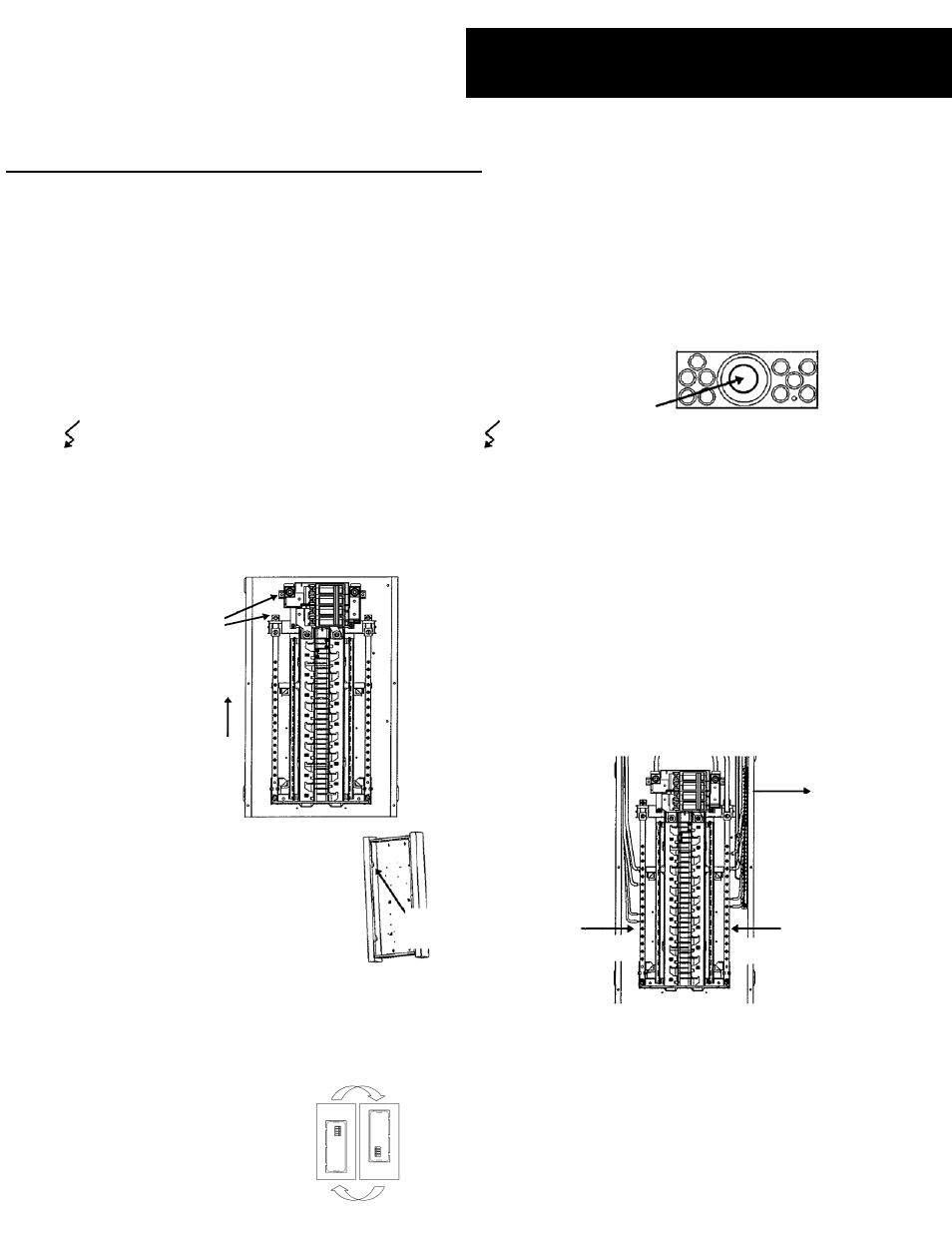
1. Remove Front
Slip front and accessory package back into carton to
protect finish.
2. Remove Interior (optional)
3. Mount Box
For
Flush Mount line up front box
edge with finish wall surface and
screw or nail to stud through small
KO’s in box side. For
Surface Mount
screw or nail through keyhole slot in
back of box.
TOP OR BOTTOM FEED
The load center will easily accommodate incoming
electrical service from the top or bottom. Rotate the entire
load center enclosure if a bottom feed configuration is
required.
4. Remove KO’S for all main and branch
circuits.
Knockout Center
KO inward then
Outer Rings
First knock center KO inward. Outer rings should be
alternately pried up or driven in one at a time.
5. Pull incoming service and branch circuit
wiring into box
.
6. Replace interior
Reinstall mounting screws removed in Step 2.
Back Out
Mounting
Screws and
save for reuse.
(Both sides)
Slide Interior
Up to clear
tabs and
remove.
7. Wire main, neutral, and equipment
ground.
Refer to rating label inside equipment for proper
tightening torque. Wire neutral and equipment ground
only in direction indicated by arrows. If required, ground
and bond neutral to box using screw provided.
Equipment
Ground
Neutral
Neutral
Nail or
Screw
8. Optional wiring of neutral and ground
The neutral crossbar may be removed to provide optional
neutral and ground wiring as follows: