GE Industrial Solutions Distribution Cable Harness User Manual
Page 4
GEH-6255 Installation Instructions
The electronic signals supported by the Distribution
Cable Harness vary depending on the type of trip unit
used; a list of supported functions is as follows:
Spectra
®
RMS Breaker with microEntelliGuard
TM
or
MicroVersaTrip
®
PM Trip Unit
• Control power (+24vdc)
• Control power (-common)
• System communications (Comm. +)
• System communications (Comm. -)
• Voltage A f (must be from Voltage Module or Voltage
Conditioner Plate or Voltage Conditioner Assembly)
• Voltage B f (must be from Voltage Module or Voltage
Conditioner Plate or Voltage Conditioner Assembly)
• Voltage C f (must be from Voltage Module or Voltage
Conditioner Plate or Voltage Conditioner Assembly)
Spectra
®
RMS Breaker with MicroVersaTrip
®
Plus or
microEntelliGuard
TM
(with Basic Metering) Trip Unit
• Control power (+24vdc)
• Control power (-common)
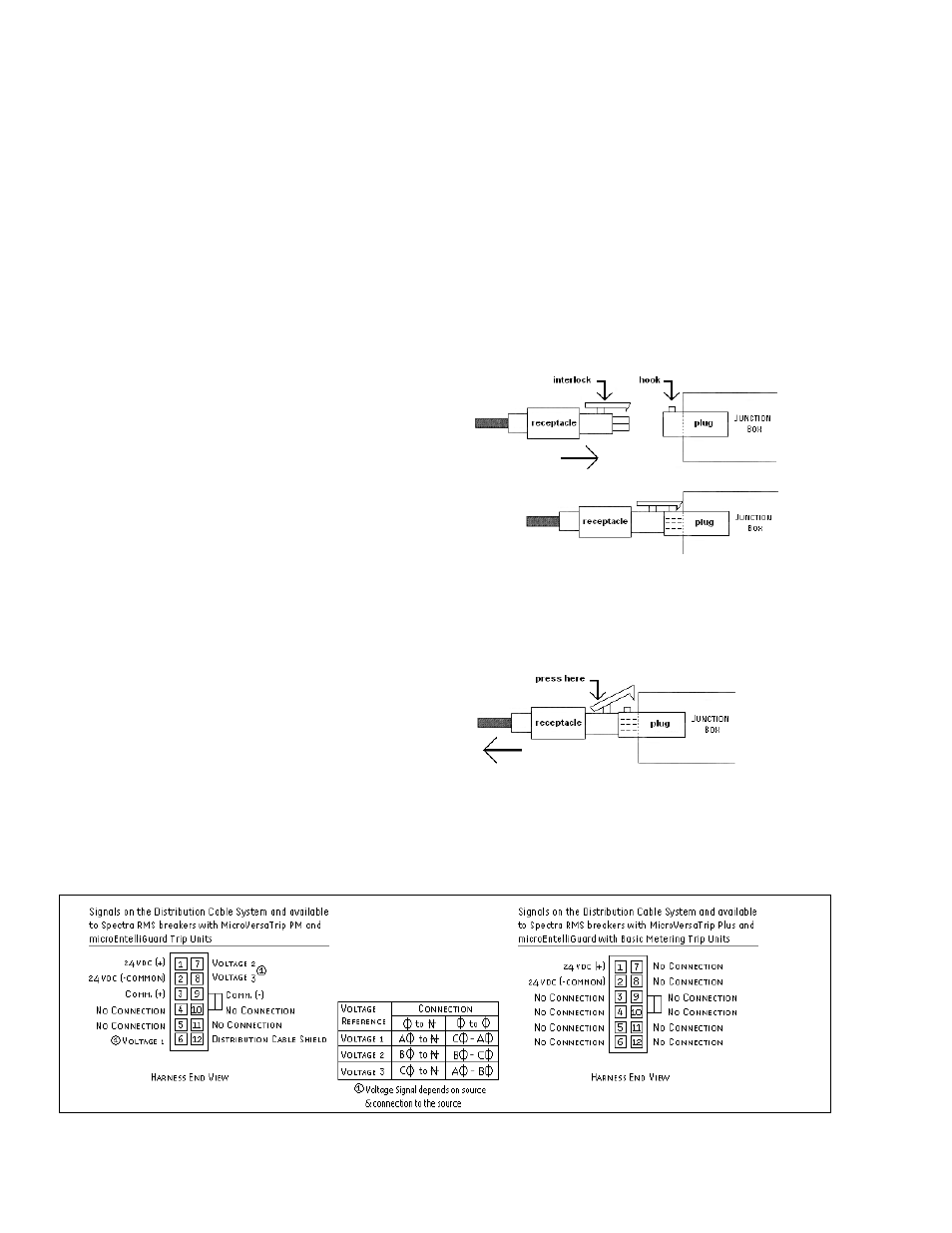
Figure 3 shows the connector pinout for the Distribution
Cable Harness for each type of trip unit.
Connections
The Distribution Cable Harness contains a 12-pin
receptacle connector on each end. The connectors are
keyed so they cannot be inserted incorrectly into a
mating 12-pin plug connector.
To connect the end of the Distribution Cable Harness to
another Distribution Cable Accessory, align the harness
receptacle interlock with the plug hook of the mating
Distribution Cable accessory and insert the receptacle
into the plug until the interlock and hook overlap and
catch (see Figure 4).
To disconnect the Distribution Cable Harness, press
down at the rear of the receptacle interlock until the
interlock clears the hook, and remove the receptacle
(see Figure 5).
Figure 4. Side view of receptacle-plug connection insertion.
Figure 3. End view of Distribution Cable Harness detailing available pinout connections.